background image

The WEED-IT Quadro system is sold and supported in Australia and Canada by Croplands 

Equipment Pty Ltd
50 Cavan Road,
Dry Creek
SA 5094
+61 (0)8 8359 9300
www.croplands.com.au
Last changed: 23/3/2020

©


Copyright


Rometron


B.V.


2020

This


manual


was


created


by


Croplands 

and 

Rometron


BV


in


The


Netherlands


and


is


subject


to


copyright.


No


part


of


this


publication


may


be


multiplied,


reproduced,


stored


and/or


published,


in


any


way


whatsoever,


without


the


prior


written


consent


of


the


publisher.


For


further


information


please


refer


to:

Rometron


B.V.

Hoge


Wesselink


8

7221


CJ


Steenderen

+31 (0)575 451111

www.weed-it.com

Patented and patents pending

All rights reserved

Disclaimer

Although all information in this manual was carefully checked and is believed to be correct, such cannot be

guaranteed. Rometron B.V. cannot be held responsible for any damage, direct or indirect, resulting from the use

or misuse of the information in this manual, or the instructions described herein. This is also true if Rometron

was aware of the possibility of such a damage. Your statutory rights are not affected.

Without prejudice.

Original instructions

Subject to change without prior notice. This User Manual WEED-IT Quadro, version 2.0, was last updated March

2020.

2


/


82


|


WEED-IT


Quadro


|


User


Manual


-

BT-UMWEEDQ-B

Summary of Contents for WEED-IT Quadro

Page 1: ...HT OMMICRO A 1 WWW CROPLANDS COM AU WEED IT QUADRO USER MANUAL BT UMWEEDQ B ...

Page 2: ...oge Wesselink 8 7221 CJ Steenderen 31 0 575 451111 www weed it com Patented and patents pending All rights reserved Disclaimer Although all information in this manual was carefully checked and is believed to be correct such cannot be guaranteed Rometron B V cannot be held responsible for any damage direct or indirect resulting from the use or misuse of the information in this manual or the instruc...

Page 3: ...OFF 2 5 Forced shutdown 2 6 Before each use 3 Identification of parts 3 1 System overview 3 2 Control unit 3 2 1 On Off switch 3 2 2 Display 3 2 3 Function keys 3 2 4 Navigation keys 4 Using WEED IT 4 1 Main menu and Service mode 4 2 Pressure check 4 3 Sensors check 4 4 Cleaning nozzles 4 5 Reading job productivity 4 6 Changing the PWM mode 4 7 Setting the nozzle type 4 8 Changing application rate...

Page 4: ... 67 69 71 71 71 71 72 72 74 75 8 Troubleshooting 8 1 Messages 8 2 Warnings and errors overview 9 Specifications 10 Menu options overview 10 1 Service mode 10 2 User Settings 11 WEED IT software information 12 Calibration settings form 12 1 General Machine Information 12 2 Dealer menu configuration settings 12 2 1 Menu 200 Console and sensor information 12 2 2 Menu 201 Power Supply Unit PSU 12 2 3 ...

Page 5: ...eneral maintenance instructions Section 6 Instructions for cleaning storage and transport Section 7 Control unit reference section with a description of available menus Section 8 Troubleshooting information Section 9 Specifications Section 10 Menu options overview Section 11 Calibration settings form An index has been added to make finding the required information easier 1 1 Conventions bold type ...

Page 6: ...This icon draws attention to helpful information and or tips tricks for correct use of the WEED IT system 6 82 WEED IT Quadro User Manual BT UMWEEDQ B ...

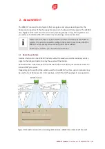
Page 7: ...he WEED IT automatically senses which options are available Contact your dealer if you need more information 2 1 Operating principle A series of sensors on the WEED IT detects where the weeds are and immediately sends a signal to the relevant nozzle to spray the weed with herbicide Each sensor has 4 channels each channel covers 25 cm of 100 cm per sensor or covers 10 inches of 40 per sensor Depend...

Page 8: ...instructions Please make sure that colleagues and or customers read all safety instructions before they start using a WEED IT system Use the Control unit for operating the system The Control unit consists of a display and a series of buttons in a waterproof casing See Control unit on page 18 for more information on use of the Control unit 2 2 Important safety information Please read the safety inf...

Page 9: ...rized use is entirely at the user s own risk Documented and authorized use also implies that the operator and safety instructions as issued by the manufacturer are followed strictly and that only original WEED IT parts are used The WEED IT system may only be operated maintained and repaired by people with the appropriate level of knowledge about the possible dangers Any unauthorized changes and or...

Page 10: ...sport items such as lights safety signs safety covers etc Never leave the driver seat while driving the vehicle Note that the behavior of the vehicle as well as steering and brake characteristics are influenced by the WEED IT system and the counterweights Make sure you have sufficient steering and brake power Only put the machine into service when all safety covers are in place and in the right po...

Page 11: ...t no cables are trapped when working on the machine Damage to the cables may cause a short circuit this increases the chance of a fire The charging capacity for the battery should be more than 100A If necessary put the vehicle in a lower gear so that the engine generates more revolutions per minute to ensure that the alternator generates more power When using an extra battery on the spraying rig p...

Page 12: ...ides or toxic agents always wear protective clothing such as protective gloves protective clothing and protective glasses Check for a possible interaction between the herbicide and certain sensitive parts of the machine Don t use any herbicides that have the tendency to stick or coagulate Crop protection machines may not be filled with surface water in order to protect humans animals and the envir...

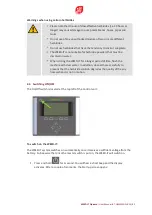
Page 13: ...ime flush the machine with clear water In addition clean all hoses carefully to prevent that the herbicide solution degrades the quality of the any hoses when it is not in motion 2 4 Switching ON OFF The On Off switch is located at the top left of the Control unit To switch on the WEED IT The WEED IT system switches on automatically once it receives a sufficient voltage from the battery So be awar...

Page 14: ...ly press All settings and counters are stored 2 The screen shows the WEED IT logo and the text Shutting down 3 The machine switches off after a short delay If you accidentally press restart the machine by pressing the F1 key Restart within 2 seconds 2 5 Forced shutdown In the rare event of a system failure use the On Off switch to force a shutdown 14 82 WEED IT Quadro User Manual BT UMWEEDQ B ...

Page 15: ...ed properly the pressure indicated by the control unit is binding The pressure on the blue manometer is usually higher at the right pressure than 42 psi to obtain the actual 42 psi If you need to adjust the pressure pull and turn the dark red knob Push the dark red knob when you have adjusted the pressure to a satisfactory level 4 Check the system for leakages 5 Press to flush the system with wate...

Page 16: ... this page is left intentionally blank 16 82 WEED IT Quadro User Manual BT UMWEEDQ B ...

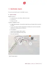
Page 17: ...e WEED IT needs a Pump spraying system to provide the required amount of liquid to all the nozzles on the boom a pressure accumulator valve Croplands PAV or Ramsay and a small air compressor optional to maintain pressure to the valve an Air regulator Speed sensors supplied with the system Pressure sensor supplied with the system Flow sensor optional Figure 3 1 System overview WEED IT Quadro User M...

Page 18: ...gulator is installed between the air compressor and the PAV Ramsay valve The unused fluid flow goes back into the tank via a return line dump line Make sure that the primary valve used to draw the liquid from the tank and all couplings are absolutely water tight Even the smallest leak will cause pressure variations or even pump failure Leakage may also cause dripping from the nozzles instead of sp...

Page 19: ...tems Function keys See Function keys on page 22 The function of these five keys depends on the menu level Each key corresponds with a function displayed in the screen Navigation keys See Navigation keys on page 23 Use the navigation keys to select a value or to move through the items in the menu Menu key Use the Menu key to change the menu level the menu within a level or to access a different use...

Page 20: ...screen opens 3 2 2 Display When you switch on the WEED IT system the Start up screen opens Immediately after that the Main screen opens The screen above shows a system that has 20 sensors 10 on either side identified as A through J The top of the screen shows a number of important values subject to system settings Refer to Main menu options on page 37 for information on specific main menu options ...

Page 21: ...al distance traveled in km or milesfrom the moment the machine was turned On The counter automatically resets when the machine is turned Off Uptime The time in hours that has passed since the machine was turned on The counter automatically resets when the machine is turned Off Spray mode set PWM OFF Sport Cover Usage If a flow meter is connected liquid use in L Ha is displayed instead of the uptim...

Page 22: ...sabled sensor Menu bar The lower part of the screen shows a menu bar with icons These illustrate the function of each Function key Please note that the function of each key changes depending on the selected menu Refer to Main menu options on page 37 for more information Warnings and messages In case of problems a message appears in the screen just below the speed bar If there is more than 1 messag...

Page 23: ...ning on the headlands In other menus the F3 function key is mostly used to confirm a setting 3 2 4 Navigation keys The navigation keys consist of 4 arrow keys Left Right Up Down and a Menu key in the middle Use the arrow keys to select a value or to move through items in a menu Press to select a menu Press repeatedly to browse through available menus Press and hold for one second to enter the Serv...

Page 24: ... this page is left intentionally blank 24 82 WEED IT Quadro User Manual BT UMWEEDQ B ...

Page 25: ...eak will result in pressure variations or even complete pump failure Air in the lines may result in dripping instead of spraying from the nozzles For all valves and fittings use plastic stainless steel or chromed brass Never use galvanized fittings because the use of glyphosate and related substances will cause corrosion The system has narrow fan nozzles for spot spraying Check the nozzles regular...

Page 26: ... with clean water to avoid clogging Sensitivity of the sensors may have to be adjusted depending on circumstances Refer to Changing sensitivity on page 31 for more information We recommend to use at least a 100 mesh pressure filter in your sprayer to prevent solenoid valve clogging or damage due to particles 4 1 Main menu and Service mode Two User levels are available Main menu This is the default...

Page 27: ...ection is active the leaf icon will flash 7 Activate nozzles by supplying chlorophyl green plant material in the corresponding sensor channels 8 Press again to stop 9 Press to return to the Main screen Additionally use one of the other Service mode options in Nozzle cleaning menu 102 on page 43 Replace a faulty or damaged sensor with a new one If no replacement sensor is available move a functioni...

Page 28: ... no plants in the detection line to prevent the corresponding nozzles from spraying continuously in step 6 2 Stop the vehicle 3 Enter the Service mode 4 Press repeatedly until menu 102 opens 5 Press to activate Detection As long as Detection is active the leaf icon will flash 6 Activate the nozzle by supplying chlorophyl green plant material in the corresponding sensor channel 7 Press again to sto...

Page 29: ...s briefly a number of times until menu 104 opens 4 Press the Mode function key to select the PWM mode you wish to use 5 Adjust the available parameters to match your nozzle type and preferred spray rates 6 Press OK to confirm All sensors are reconfigured and the system restarts 4 7 Setting the nozzle type Follow the steps below if you have replaced nozzles on the WEED IT by a new type 1 Stop the v...

Page 30: ...the application rate 1 Stop the vehicle 2 Enter the Service mode 3 Press briefly a number of times until menu 104 opens 4 Use the Up Down navigation keys to select the Spot and or Cover parameter if necessary use the Left Right navigation keys to change the application rate The spot parameter determines the amount of herbicide mix that is applied to the weeds that are detected by the system The he...

Page 31: ...o compensate for strong winds Please note that spraying during very strong winds is not advised Larger margins should be used in rough terrain with unstable booms or around contour banks From the Main screen 1 Press briefly to open the Preset menu 2 Press to change the margin By default the margin presets are defined as follows 1 200 mm 2 230 mm 3 270 mm 4 300 mm advised for rough terrain contour ...

Page 32: ...mber means a low sensitivity Figure 4 1 Preset number 2 selected You may have to experiment to find the appropriate setting Check the display to verify sensor response A series of vertical bars under the sensor icons indicates the activity of each sensor Refer to Preset menu options on page 39 for more information on presets 4 11 Machine on hold Use the Hold function to temporarily stop spraying f...

Page 33: ...overload and increases the possibility of a fire When servicing the electrical installation always remove the terminal of the battery Always connect the battery in the proper order first connect the terminal followed by the terminal When disconnecting do the same in reverse order The terminal should have a protective cover to avoid the possibility of a short circuit explosion Avoid sparks and open...

Page 34: ...even though it is not as wide as you would like it to be and communication is not interrupted Make sure that the nozzle configuration is correct for this sensor distance and height Also adjust the offset because this changes if the sensor s position on the boom is changed Contact your supplier for support 5 2 Nozzle maintenance We recommend to use at least a 100 mesh pressure filter in your spraye...

Page 35: ... prevent that the herbicide solution degrades sensitive materials General storage instructions Always store the machine in a dry warm place Ensure that all pressure is released from the system before storing it Stop the pump and press When the machine is stored for a longer period of time disconnect the system from the battery The easiest way to do this is to disconnect the main power plug Use of ...

Page 36: ... anti freeze fluid to the fluid system Make sure the anti freeze fluid is appropriate for the circumstances and that it is well distributed through your sprayer s fluid system This includes the added WEED IT spray related parts such as the solenoid valves and the ramsey valve General cleaning and transport instructions Do not clean the system with a high pressure nozzle control panel power box sen...

Page 37: ...enu options below 2 Service mode refer to Service mode on page 40 7 1 Main menu If the Main menu is active the Main screen is open and the main menu is selected Press briefly to browse through available menus Main menu and Preset menu If no key is pressed for 3 seconds the system will take you back to the Main screen 7 1 1 Main menu options The main menu offers the options for regular use of the W...

Page 38: ... display shows the short term activity in a histogram S slow the display shows the long term activity in a histogram All the display shows all activity from the moment the machine was switched on Flush Use this key to flush the system During flushing all nozzles are opened simultaneously Use this option for cleaning the system or for checking that all nozzles are functioning Hold Use this key to t...

Page 39: ...uses a certain margin when spraying a target This margin varies from 200 300 mm and specifies the distance before and after the weed to be sprayed One of four predefined margins can be selected while driving the vehicle The number of the selected margin is displayed to the left of the icon The margin setting is often used to compensate for the spray displacement caused by heavy winds or uneven ter...

Page 40: ...ervice mode The global information screen opens Press briefly a number of times to browse through the available menus Service mode offers the following menus 100 Information Offers general information about various WEED IT components 101 Warnings Shows warnings issued by the system 102 Nozzle cleaning Tests sensor and nozzle activity 103 Job menu Displays productivity status of individual jobs 104...

Page 41: ...hine life Max speed Maximum speed that is possible with current machine settings Press this key to leave the Service mode and to return to the Main screen Press this key to select the Left boom L or the Right boom R The underlined one is the selected one Press this key to enter the user configuration menu First sensor Press this key to open information on the first sensor Note that the Function ke...

Page 42: ...lowing meaning Press this key to leave the Service mode and to return to the Main screen Press this key to turn the selected sensor on or off Press this key to go to the Previous sensor Press this key to go to the Next sensor 7 2 2 Warnings menu 101 In the Main screen warnings are displayed directly below the speed bar If there are no warnings or messages to display a clock is shown Only one messa...

Page 43: ...nu is only available when the vehicle is not moving Use the Nozzle cleaning menu to flush nozzles test detection test solenoid valves check nozzles Press the Exit key to leave the Service mode The main screen opens Press the Chase key to activate nozzles one by one with a short burst Press the Detection key test nozzles Holding a leaf under a sensor should activate the corresponding nozzle Press t...

Page 44: ...iquid Total volume of liquid sprayed for the current job Usage Total volume of liquid used per Ha Liquid divided by Area for the current job Use this key to return to the Main menu Use this key to start a new job Please note that a maximum of 8 jobs can bed saved If you start a new job the data for the first job is deleted By default the details in menu 103 are stored per job If you save data per ...

Page 45: ...d in various modes Spot spraying Full coverage Dual spot cover By default PWM Pulse Width Modulation is disabled If PWM is disabled menu 104 looks like this After changing the PWM mode or the application rate all sensors must be reconfigured Press the OK key to confirm the new settings and update all sensors This may take a couple of seconds The system automatically restarts Spot spraying mode Pre...

Page 46: ...type is used When mounting a different type of nozzle use menu 104 to select the appropriate type before proceeding This nozzle is used for all PWM modes Use the Left Right navigation keys to select the appropriate nozzle type 5 Press OK to confirm All sensors are reconfigured and the system restarts Only use the nozzle types that you can select in the software The nozzle type is usually engraved ...

Page 47: ...se the nozzle types that you can select in the software The nozzle type is usually engraved in the top surface of the nozzle Press the OK key to confirm the new settings and update all sensors The system automatically restarts WEED IT Quadro User Manual BT UMWEEDQ B 47 82 ...

Page 48: ...verage rate This mode also offers a nozzle setting parameter Only use the nozzle types that you can select in the software The nozzle type is usually engraved in the top surface of the nozzle Press the OK key to confirm the new settings and update all sensors The system automatically restarts 7 3 User settings menu The User settings menu allows you to set basic configurations for your WEED IT syst...

Page 49: ...display contrast 7 3 2 Units 151 Use the Up Down navigation keys to select the parameter you wish to change Use the Left Right navigation keys to change the setting Press the OK key to confirm settings Speed Select the unit for speed that you would like to use Dist Select the unit for distance that you would like to use Fluid Select the unit for Fluid that you would like to use Pressure Select the...

Page 50: ...of time The clock is powered by its own lithium battery that will keep the clock running for approximately one year When the battery has been replaced you will have to set the clock to the current date and time If WEED IT detects an impossible date when it is turned on menu 153 will automatically open Use the Up Down navigation keys to select the parameter you wish to change Use the Left Right nav...

Page 51: ... speed bar In the Main menu only one message can be displayed at a time If more than one message is pending or if multiple errors occur at the same time each message is shown for a few seconds Use the Message menu to check for any other messages To access the Message menu 1 Press for 1 second to enter the Service mode 2 Repeatedly press until menu 101 opens 3 The header indicates the number of war...

Page 52: ...ge for a few seconds before the next one is displayed To see all messages simultaneously use menu 101 When WEED IT is turned off all messages are deleted Only the dealer can then retrieve old messages from a special dealer menu 8 2 Warnings and errors overview See also Warnings menu 101 on page 42 Errors Warnings Details How to resolve ERROR A serial problem has occurred This message appears whene...

Page 53: ... low Appears whenever battery voltage drops below a certain pre determined value The message reports the lowest voltage measured during this session For example Even though the battery voltage seems to be sufficient it is possible that the voltage sometimes briefly drops below the lower limit Check the lowest battery voltage in the Message menu 101 The lower limit is displayed to the right of the ...

Page 54: ...n place and order a replacement sensor from your supplier and have them install it If this doesn t solve the problem try swapping the next sensor on the boom left D with this sensor If this does not solve the problem Check the Control unit connection cables between the Power converter and the Control unit for physical damage Do the same for all of the cables running from the power converter to the...

Page 55: ... in place and order a replacement sensor from your supplier and have them install it If this doesn t solve the problem try swapping the next sensor on the boom left D with this sensor If this does not solve the problem Check the Control unit connection cables between the Power converter and the Control unit for physical damage Do the same for all of the cables running from the power converter to t...

Page 56: ...l unit does not have a valid serial number Contact your supplier immediately and have them replace the Control unit Sensor firmware too old The version of the firmware inside the sensor is too old If the error occurs after a sensor replacement your supplier must update the sensor firmware If this problem occurs without changing the sensors there is a communication problem between one of the sensor...

Page 57: ...here is a communication problem between one of the sensors and the Control unit Follow the same procedure as you would in case of a COM error The sensor with the communication issue is in this case not the one with the x but the sensor that shows an unusual serial number in the sensor information menu 100 Configure Restored to factory default Contact your supplier immediately WEED IT Quadro User M...

Page 58: ... check this for the pneumatic hoses and fittings connecting the compressor to the PAV Ramsay valve Check the supply pressure on the pressure regulator to the PAV Ramsay valve this should be within 0 5 1 bar of the pressure on the spray line Increase the pump flow Increase the PAV Ramsay valve air pressure Check the mounted nozzle type and make sure they have a flow of less than 0 6 gallon min at 3...

Page 59: ...ing the compressor to the Ramsay valve Check the supply pressure on the pressure regulator to the PAV Ramsay valve this should be within 0 5 1 bar of the pressure on the spray line Decrease the pump flow Decrease the PAV Ramsay valve air pressure Check the return line from your PAV Ramsay valve and make sure this is free of obstructions and unclogged If none of the above steps solve your problem p...

Page 60: ...sor screens in menu 100 and check sensor firmware version and status for any anomalies New sensor found A new sensor has been detected If this occurs after a sensor replacement your supplier will need to confirm this message and set up the new sensor If this problem occurs without changing the sensors this indicates a communication problem between one of the sensors and the Control unit Follow the...

Page 61: ...ol unit for physical damage Check the Power converter for any damage Open the lid and check for any signs of short circuits or moisture inside Contact your supplier immediately and report any findings Direction arrow in main screen does not point upwards while I drive on a straight track Direction arrow wiggles while I drive on a straight track The speed sensors are faulty or the speed sensors are...

Page 62: ...Messages Details HOLD WEED IT is in HOLD mode Manual The nozzles are being controlled manually Flushing The nozzles are being flushed 62 82 WEED IT Quadro User Manual BT UMWEEDQ B ...

Page 63: ...lant the minimum leaf area detected is approximately 2 cm2 Electronic specifications Supply voltage 12 VDC Power consumption 10 to 20 W per sensor Current protection 80 A fuse System voltage 48 VDC Detection specifications Detection channels 4 Detection distance 1100 mm 43 Channel width 250 mm 10 LED wavelength 475 nm Light intensity 160 lm Sensitivity 2 cm2 minimum Sample frequency 28000 Hz Fluid...

Page 64: ... x M6 bolt Thread length 8 mm bracket thickness Do not use longer bolts to prevent damage to the detection sensors Detection sensor angle Maximum 22 forward Wheel speed sensors Max 8 mm from wheel ring holes 64 82 WEED IT Quadro User Manual BT UMWEEDQ B ...

Page 65: ...u Histogram Flush Hold Counter Preset menu Histogram Flush Hold Preset Counter 10 1 Service mode Information 100 Back to the main screen Select the Left or right boom Configure First sensor WEED IT Quadro User Manual BT UMWEEDQ B 65 82 ...

Page 66: ...ivated one by one short Activate detection Nozzles activated one after the other Activate nozzles in random order simulating PWM control Job 103 Back to the main screen New job Reset Confirm Go to the previous job Refresh information Job 103 Previous Jobs Back to the main screen Go to the previous job Go to the next job PWM Nozzle selection 105 Back to the main screen PWM mode Confirm setting Cove...

Page 67: ...k to the main screen Confirm setting Units 151 Back to the main screen Confirm setting Options 152 Back to the main screen Confirm setting Set time date 153 Back to the main screen Confirm setting WEED IT Quadro User Manual BT UMWEEDQ B 67 82 ...

Page 68: ... this page is left intentionally blank 68 82 WEED IT Quadro User Manual BT UMWEEDQ B ...

Page 69: ...________________________ Update Detection sensors Control unit Power Converter Installation date ___________________________________ Dealer ___________________________________ Update Detection sensors Control unit Power Converter Installation date ___________________________________ Dealer ___________________________________ WEED IT Quadro User Manual BT UMWEEDQ B 69 82 ...

Page 70: ... this page is left intentionally blank 70 82 WEED IT Quadro User Manual BT UMWEEDQ B ...

Page 71: ...__________________________________________________ Boom width ______________________________________________________ Serial ______________________________________________________ Dealer ______________________________________________________ Customer ______________________________________________________ 12 2 Dealer menu configuration settings 12 2 1 Menu 200 Console and sensor information Menu 200...

Page 72: ...3 Menu 203 Configuration Speed Unit Source Pulses Pull Volt ____________________ ____________________ ____________________ ____________________ ____________________ Check speed sensor functioning in menu 211 Flow Enable Pulses Pull ____________________ ____________________ ____________________ 72 82 WEED IT Quadro User Manual BT UMWEEDQ B ...

Page 73: ...unctioning can be checked in menu 211 Pressure 1 Enable Low High Cal Offset Smooth Type V I ____________________ ____________________ ____________________ ____________________ ____________________ ____________________ ____________________ Mostly a pressure sensor is a voltage sensor V not a current sensor I Smooth can stay at 50 00 Pump Pump refers to the small ARB air compressor to supply air to ...

Page 74: ...ach individual sensor Humidity Humidity Temperature ____________________ ____________________ ____________________ 12 2 4 Menu 205 Sensor settings Configure the menu 205 position of each sensor Configure the track for the whole system Margin ___________ same for each sensor Preset is indicated if 4 margin presets are enabled Track ___________ make sure you press OK for 2 seconds to confirm for all...

Page 75: ...the correct nozzle height h and distance d from the detection line to the nozzle line The Max indicates the maximum speed that is possible with the WEED IT it is based on the smallest distance and highest height set amongst all sensors The speed that is shown in between the arrows is the optimum speed programmed in menu 203 WEED IT Quadro User Manual BT UMWEEDQ B 75 82 ...

Page 76: ...2 6 Menu 214 Margin presets Only applicable when menu 204 5 option user wind margin is enabled Preset 1 Preset 2 Preset 3 Preset 4 ____________________ ____________________ ____________________ ____________________ This WEED IT Quadro system was configured and tested Date confirmed ____________ 76 82 WEED IT Quadro User Manual BT UMWEEDQ B ...

Page 77: ...n during spraying 31 PWM mode 29 Sensitivity 31 Spraying mode 29 Chase key 43 Cleaning Nozzles 28 Cleaning instructions 36 Clock 50 Components in the system 8 Configuration 150 49 Control unit 8 18 Control unit reference 37 Conventions 5 Couplings 18 25 Cover parameter 46 Crop protection solutions Safety 12 Current job 44 Current job menu 103 44 Current speed 21 D Date and time 50 Dealer menu conf...

Page 78: ... M Machine on Hold 32 Main menu 26 37 Main screen 14 26 Maintenance General 33 Nozzles 34 Sensors 34 Margin 21 26 Margin during spraying Change 31 Margin key 39 Maximum possible speed 41 Measurement key 39 Melody key 43 Menu 200 Console and sensor information 71 Menu 201 Power Supply Unit 72 Menu 203 Configuration 72 Menu 205 Sensor settings 74 Menu 206 Sensor setup 75 Menu 214 Margin presets 76 M...

Page 79: ...or Channels 7 Information menu 41 Maintenance 34 Presets 31 Sensitivity 26 31 Windows 26 Sensors check 27 Sequencing key 43 Service mode 40 Access 23 26 Set time date menu 153 50 Software information 69 Speed 21 26 Spot spraying mode 45 Spraying mode Change 29 Spraying modes 45 Start up of the system 20 Start up screen 13 19 Storage instructions 35 Store data By day 44 By job 44 Sun 21 Surface 21 ...

Page 80: ...V Values 21 W Warning icon 5 Warnings 52 Herbicides 13 Menu 42 Warnings 101 42 Warnings errors 51 WEED IT definition 7 80 82 WEED IT Quadro User Manual BT UMWEEDQ B ...

Page 81: ...WEED IT Quadro User Manual BT UMWEEDQ B 81 82 ...

Page 82: ...uipment Ltd PO Box 2004 Stortford Lodge Hastings 4120 Location 1422 Omahu Road Hastings 4120 New Zealand Freecall 0800 106 898 Freefax 0800 1 17 71 1 Email sales croplands co nz Website www croplands co nz Your nearest Croplands Dealer can be found in the dealer section on the Croplands website CANADA Croplands Equipment Pty Ltd PO Box 2441 Dry Creek SA 5094 Australia Phone 1403 831 3913 Email add...

Reviews: