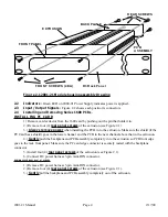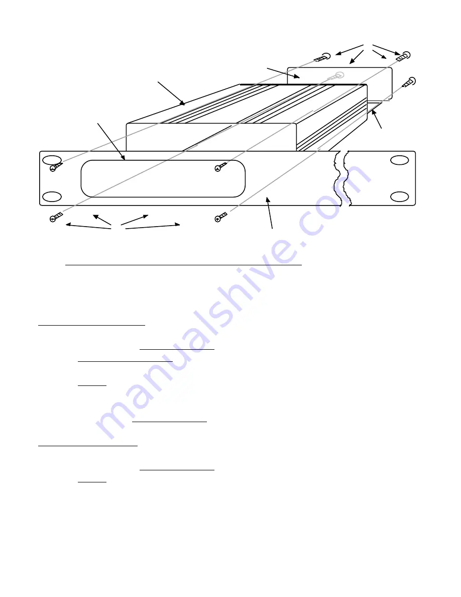
EXTRUSION
BACKPLANE
REAR SCREWS
(4EA)
FRONT SCREWS (4EA)
FRONT PANEL
PCB
ASSEMBLY
R3 Rack Panel
Figure 2.1 2001-21 Module housing assembly Drawing
2 . 2
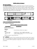
Indicators - Green LED on 2000-01 Power Supply indicates power is applied..
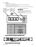
2 .3 Input / Output Signals - Figure 2.2 shows each position’s connectors.
2 . 4
Installing and Removing Series 1600 PCBs -
INSTALLING PC CARD
1) Remove card extractor from the 1600 card by pushing out the pin that holds it in.
2.) Remove four (4) rear panel screws of the extrusion (see Figure 2.1).
3.) Always remove power when installing the PCB in to the extrusion. Make sure the shield (if the
PC Card has a shield) goes in the lower channel and the PCB in the next channel above that in the extrusion.
4.) Gently push the backplane and PCB assembly completely in to the extrusion so PCB front edge
goes to the rack front panel. Make sure the PC card edge connector is securely mated with the backplane
connector.
5.) Install four (4) rear panel screws of the extrusion (see Figure 2.1).
6.) Connect DC power harness 3-pin mini-DIN connector.
REMOVING PC CARD
1.) Remove DC power harness 3-pin mini-DIN connector.
2.) Remove four (4) rear panel screws of the extrusion (see Figure 2.1).
3.) Gently pull the backplane and PCB assembly completely out of the extrusion.
2001-21 Manual
Page 4
2/17/00


