2 . 5
Operation -
1.) Install PC Cards as in section 2.4
2.) Connect the ± 15 VDC harness between the 2000-01 and the extrusion backplanes
3.) Connect signals to the PC cards as needed
4.) Connect the 2000-01 power supply to 115 VAC, 60 Hz. See the Green LED on the 2000-01 is on.
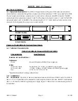
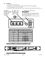
J2
J3
1
5
6
9
-15 +15
GND
Card Inputs
Outputs
- The signals
on 1600 PC cards that
go through the
opening in the
backplane
J2 - DC IN
- The +15
VDC AND -15 VDC
regulated DC voltage
from the wall power
supply
J3 - Card I/O
- DB9 female connector
PIN - FUNCTION
1,5 -
Ground
2-
Connects to
Pin 4
of the 1600 edge connector
3-
Connects to
Pin 5
of the 1600 edge connector
4 , 6 , 7 , 8 -
No Connection
9-
Connects to
Pin 15
of the 1600 edge connector
TABLE 2.0 2001-21 DB9 to Card Edge Connector Pins
TABLE 2.0 2001-21 DB9 to Card Edge Connector Pins
DB 9 PIN
1600 CARD EDGE CONNECTOR PIN
1
GND (1,18)
2
4
3
5
4
NO CONNECTION
5
GND (1,18)
6
NO CONNECTION
7
NO CONNECTION
8
NO CONNECTION
9
15
Figure 2.2 2001-21 Connectors and DB9 Pin outs
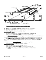
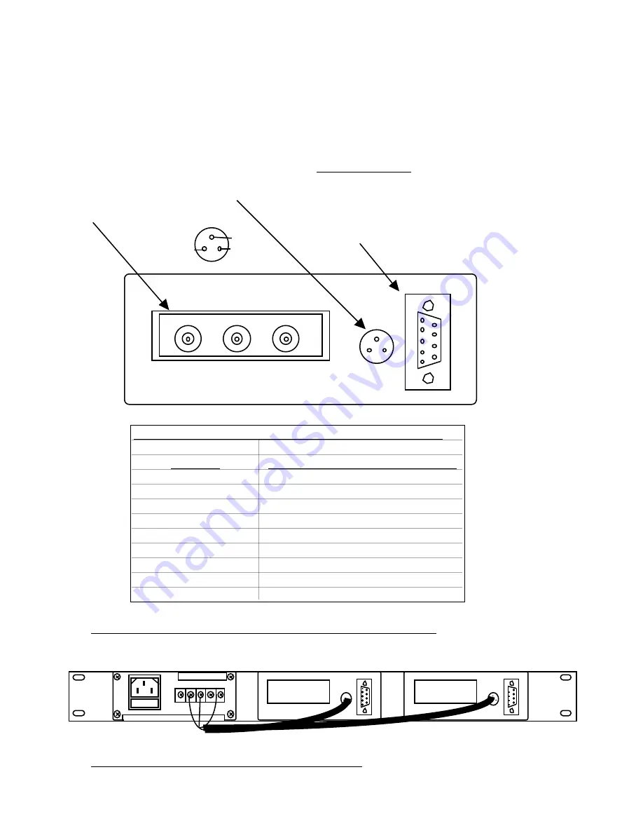
CAUTION - RISK OF ELECTRICAL
SHOCK - DO NOT OPEN!!!
-15 GND +15
C
ROSS
T
ECHNOLOGIES, INC.
90-260 VAC
7 - 63 HZ
FUSE 2 A
J2
J3
1
5
6
9
J2
J3
1
5
6
9
Figure 2.3 2001-21 DC Power Harness
2001-21 Manual
Page 5
2/17/00