AHRS500GA Series Operator’s Manual
Page 4
Doc# 7430-0060-02 Rev. A
3.2
Connections
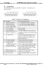
The AHRS500GA500 has a male DB-15 connector. The signals are as
shown in Table 1.
Table 1 Connector Pin Assignments
Pin
Signal
Electrical Specifications
1
RS-232 Transmit
+/- 4.5 VDC min wrt power ground.
2
RS-232 Receive
+/- 25 VDC max wrt power ground.
3
VDC Power Input
10-40 VDC normal, 9VDC emergency
4
Power Input Ground
5
No connection
Do not connect
6
No connection
Do not connect
7
RS-422 Tr A
8
RS-422 Transmit – A
2.0 VDC differential output (min) into
100 ohms. Common mode output voltage,
3VDC max.
9
Signal Ground
Capacitive coupling to internal system
ground. Should be connected to user’s
system ground to reduce RS232 and
RS422 signal noise.
10
Factory mode pin
Factory reserved; do not connect
11
Factory mode pin
Factory reserved; do not connect
12
Magnetometer
calibration input (hard
and soft iron cal)
Active: Short to power ground.
Inactive: Open circuit. (Internally pulled
to +3.3VDC through 10Kohm resistor)
13
Hardware BIT Status
Open collector, requires user pull-up
resistor. Max pull-up voltage: +15VDC
Max current sink: 10ma.
14
RS-422 R A
15
RS-422 Receive – A
Common mode input voltage range:
3VDC wrt power ground.
N/A
Case Ground
Electrically connected to I/O connector
shell
SUNSTAR传感与控制 http://www.sensor-ic.com/ TEL:0755-83376549 FAX:0755-83376182 E-MAIL:szss20@163.com
SUNSTAR自动化 http://www.sensor-ic.com/ TEL: 0755-83376489 FAX:0755-83376182 E-MAIL:szss20@163.com


