background image


Crossbow Technology, Inc. 
41 Daggett Drive 
San Jose, CA 95134 
Phone: +1 408 965 3300 
Fax: +1 408 324 4840 
Email: info@xbow.com 

Summary of Contents for MIB300

Page 1: ...MPR MIB User s Manual Rev A August 2004 Document 7430 0021 06 ...

Page 2: ...served Information in this document is subject to change without notice Crossbow is a registered trademark DMU is a trademark of Crossbow Technology Inc Other product and trade names are trademarks or registered trademarks of their respective holders ...

Page 3: ...s for the MPR500 510 520 MICA2DOT 15 5 MPR300 MPR310 MICA 19 5 1 Schematic 19 Power 20 6 20 6 1 Battery Power 20 6 2 External Power 21 6 3 MICAz Battery Voltage Monitor 22 6 4 MICA2 Battery Voltage Monitor 22 6 5 MICA2DOT Battery Voltage Monitor 23 7 Radios 24 7 1 MICA2 and MICA2DOT 24 7 2 MICAz 26 8 Antennas 29 8 1 Radio Antenna Considerations 29 8 2 Connectors for the MICA2 and MICAz and Whip An...

Page 4: ...ISP 37 13 3 Mote Programming Using the MIB510 37 13 4 Interfaces to MICAz MICA2 and MICA2DOT 38 14 MIB600CA 42 14 1 Introduction 42 14 2 Setup Installation 42 Host Software 44 14 3 44 14 4 MIB600 Use 44 JTAG 45 14 5 45 15 Appendix A 10 100 Base T Cabling Standards 47 16 Warranty and Support Information 48 16 1 Customer Service 48 16 2 Contact Directory 48 16 3 Return Procedure 48 16 4 Warranty 49 ...

Page 5: ...latform MICAz MICA2 MICA2DOT MICA Models as of August 2004 MPR2400 MPR400 410 420 MPR500 510 520 MPR300 310 Chip ATMega128L ATMega103L Type 7 37 MHz 8 bit 4 MHz 8 bit 4 MHz 8 bit MCU Program Memory kB 128 SRAM kB 4 Type 51 pin 18 pin 51 pin 10 Bit ADC 7 0 V to 3 V input 6 0 V to 3 V input 7 0 V to 3 V input UART 2 1 2 Sensor Board Interface Other interfaces DIO I2C DIO DIO I2C Chip CC2420 CC1000 T...

Page 6: ...7430 0021 06 Rev A Page 4 q TinyOS Getting Started Guide by Crossbow Technology Inc available on the TinyOS Support Tools CDROM or the Crossbow web site at www xbow com under Support User s Manuals q The TinyOS web site at http webs cs berkeley edu tos ...

Page 7: ...e with the MPR2400 Figure 2 1 Photo of the MPR2400 MICAz with standard antenna For the dimensions of the board and locations of the mounting holes see Figure 2 2 2 2 Block Diagram and Schematics for the MPR2400 MICAz Feature Chapter Batteries 6 Radio 7 Antenna 8 Data Flash Logger 9 Atmega128 10 Expansion Connector 11 Figure 2 1 Block diagram of the MICA2 and listing of Chapters that discuss the co...

Page 8: ...MPR MIB User s Manual Wireless Sensor Networks Doc 7430 0021 06 Rev A Page 6 2 2 1 51 pin Expansion Connector ...

Page 9: ...MPR MIB User s Manual Wireless Sensor Networks Doc 7430 0021 06 Rev A Page 7 2 2 2 CC2420 Radio ...

Page 10: ...MPR MIB User s Manual Wireless Sensor Networks Doc 7430 0021 06 Rev A Page 8 2 2 3 Battery ADC1 ...

Page 11: ...ful interference to radio communications There is no guarantee that interference will not occur in a commercial environment Howe ver operation of this equipment in a residential area is likely to cause harmful interference which can be determined by turning the equipment off and on If this is the case the user is encouraged to try and correct the interference by one or more of the following measur...

Page 12: ...4x0 without an antenna Right Top and plan views showing the dimensions and hole locations of the MICA2 PCB without the battery pack 3 2 Block Diagram and Schematics MPR400 410 420 Feature Chapter Battery Ext Power 6 Radio 7 Antenna 8 Data Flash Logger 9 Atmega128 10 Expansion Connector 11 Figure 3 2 Block diagram of the MICA2 and listing of Chapters that discuss the components in greater detail MM...

Page 13: ...306 01 A MICA2 MPR410CB 433MHZ B 2 6 Friday March 21 2003 Title Size Document Number Rev Date Sheet of AVCC R10 1M L2 C18 4 7pF RADIO DATA L4 C14 Y4 14 7456MHZ 2 1 2 1 C19 13pF C13 R9 1M C6 001uF PDATA L1 BEAD 0805 C11 001uF L3 J5 MMCX 1 2 3 VCC R13 27 4K C16 001uF AVCC J3 HDR 2 X 1 X 1 1 2 1 2 U3 CC1000 21 1 5 9 15 3 4 10 11 12 13 18 17 23 24 25 26 27 28 VCC AVCC AVCC AVCC AVCC RF_IN RF_OUT L1 L2...

Page 14: ...AC GPIO AC PW 0 7 3 2 4 51 pin Expansion Pads Location J22 THRU1 PW4 AC ALE THRU2 PROG_MISO UART_TXD0 PWM0 I2C_DATA ADC 0 7 PW1 PW 0 7 I2C_CLK ADC6 THRU3 PW2 USART1_RXD SPI_SCK BAT_MON 6310 0306 01 A MICA2 MPR410CB 433MHZ CROSSBOW TECHNOLOGY INC B 4 6 Friday March 21 2003 Title Size Document Number Rev Date Sheet of PW6 INT0 UART_RXD0 UART_TXD0 PW0 PW1 PW2 PW3 PW4 PW5 PW6 ADC7 ADC6 ADC5 ADC4 ADC3 ...

Page 15: ...PC0 A8 PC1 A9 PC2 A10 PC3 A11 PC4 A12 PC5 A13 PC6 A14 PC7 A15 PD0 I2C_CLK PD1 I2C_DATA PD2 RXD1 PD3 TXD1 PD4 IC1 PD5 XCK1 PD6 T1 PD7 T2 PE0 RXD0 PE1 TXD0 PE2 XCK0 PE3 OC3A PE4 OC3B PE5 OC3C PE6 T3 PE7 IC3 PF0 ADC0 PF1 ADC1 PF2 ADC2 PF3 ADC3 PF4 TCK PF5 TMS PF6 TDO PF7 TDI AVCC AREF PEN RST XTAL1 XTAL2 PG0 WR PG1 RD PG2 ALE PG3 TOSC2 PG4 TOSC1 USART1_CLK C21 1uF FLASH_CS WR SPI_SCK ADC2 ADC3 R21 10...

Page 16: ...IO CONTROL C32 1000pF R23 4 7K VCC C30 01uF USART1_TXD U5 AT45DB041 1 2 3 4 5 8 SI SCK RST CS WP SO UART INTERFACE UART_RXD0 UART_TXD0 CONTROL INTERFACE R19 1M LED2 U6 DS2401P 2 DQ D4 YELLOW 1 2 USART1_RXD C24 10uF 10V R27 470 I2C_CLK I2C_DATA SPI_SCK SPI_MOSI SPI_MISO CHP_OUT ADC0 RSSI RADIO DATA LED1 ADC7 C29 01uF C25 01uF R25 470 R22 1M VCC C33 1000pF LED3 FLASH_CS FLASH_CS VCC D3 GREEN 1 2 FLA...

Page 17: ...DOT shown next to a US quarter a Top side and b Bottom side Typically the MICA2DOT has a 3 V coin cell battery holder attached to the bottom side but it has been removed to show the details 4 2 On board Thermistor The MICA2DOT Mote has an on board thermistor Panasonic ERT J1VR103J which is a surface mount component It is on the ATMega128 side of the board at the location labeled RT1 Its output is ...

Page 18: ...ram and Schematics for the MPR500 510 520 MICA2DOT Feature Chapter Battery Ext Power 6 Radio 7 Antenna 8 Data Flash Logger 9 Atmega128 10 Expansion Connector 11 Figure 4 1 Block diagram of the MICA2DOT and listing of Chapters that discuss the components in greater detail ATMega128L µcontroller Analog I O Digital I O Freq Tunable Radio Logger Flash Antenna Antenna 25 mm 19 peripheral pins ...

Page 19: ...1 3 Wednesday March 26 2003 Title Size Document Number Rev Date Sheet of DCLK L2 BEAD 0805 C3 0 033uF R12 1M AVCC C10 DCLK C20 13pF AVCC U3 CC1000 21 1 5 9 15 3 4 10 11 12 13 18 17 23 24 25 26 27 28 VCC AVCC AVCC AVCC AVCC RF_IN RF_OUT L1 L2 CHP_OUT R_BIAS XOSC1 XOSC2 DIO DCLK PCLK PDATA PALE RSSI POT_PWR SPI_MISO SPI_SCK L9 VCCA C18 C16 001uF C17 4 7pF R18 82 5K PALE TP17 Y1 14 7456MHZ 2 1 X2 X1 ...

Page 20: ...3 AD3 PA4 AD4 PA5 AD5 PA6 AD6 PA7 AD7 PB0 SS PB1 SCK PB2 MOSI PB3 MISO PB4 OC0 PB5 OC1A PB6 OC1B PB7 OC1C PC0 A8 PC1 A9 PC2 A10 PC3 A11 PC4 A12 PC5 A13 PC6 A14 PC7 A15 PD0 INT0 PD1 INT1 PD2 RXD1 PD3 TXD1 PD4 IC1 PD5 XCK1 PD6 T1 PD7 T2 PE0 RXD0 PE1 TXD0 PE2 XCK0 PE3 OC3A PE4 OC3B PE5 OC3C PE6 T3 PE7 IC3 PF0 ADC0 PF1 ADC1 PF2 ADC2 PF3 ADC3 PF4 TCK PF5 TMS PF6 TDO PF7 TDI AVCC AREF PEN RST XTAL1 XTAL...

Page 21: ...rmistor LED UART_TXD0 FLASH_SI VCCA VCCA R36 10K ADC1 C31 1000pF C25 01uF R29 1M D2 RED 1 2 R25 100K VCCA SERIAL_ID LED1 RT1 10 0K PW6 FLASH_SO FLASH_CLK D5 SD103AW C26 01uF PW7 C24 10uF 10V R30 4 7K VCCA R31 470 C32 1000pF U7 AT45DB041 1 2 3 4 5 6 7 8 SI SCK RST CS WP VCC GND SO RSTN VCCA R26 1M VCCA VCCA SERIAL_ID FLASH_SO ...

Page 22: ...ber 2003 The MICA Mote was the second generation Mote module used in many ground breaking research and development efforts The MPR300 310 includes a powerful Atmel ATMega128L It used an amplitude shift keying radio the TR1000 by RF Monolithics Inc 5 1 Schematic Schematics for the MPR300 410 Mote can be found at http today cs berkeley edu tos hardware hardware html ...

Page 23: ... 2000 Alkaline 3 6 to 2 7 MICA2 AA 2 2000 Alkaline 3 6 to 2 7 MICA2DOT Coin 560 Li ion 3 6 to 2 7 Care should be used in selecting the battery and its capacity to match the energy needs of the motes and their required operating span Also make sure that the temperature range and associated capacity degradation are looked at prior to deployment Table 6 2 below provides some useful guidance on curren...

Page 24: ...fe months 250 1 45 1000 5 78 3000 17 35 X NOTE In most Mote applications the processor and radio run for a brief period of time followed by a sleep cycle During sleep current consumption is in the micro amps as opposed to milli amps This results in very low current draw the majority of the time and short duration spikes while processing receiving and transmitting data This method extends battery l...

Page 25: ...4 Vref Internal voltage reference 1 223 volts ADC_Count Data from the ADC measurement of Internal Voltage reference The TinyOS component VoltageM nc can be wired into an application to provide this measurement capability The reserved keyword TOS_ADC_VOLTAGE_PORT is mapped to ADC Channel 30 in the MICAz 6 4 MICA2 Battery Voltage Monitor The MICA2 units have an accurate voltage reference that can be...

Page 26: ... reference diode S103AW as a voltage reference that can be used to measure battery voltage Vbatt Since the eight channel ATMega128L ADC uses the battery voltage as a full scale reference the ADC full scale ADC_FS voltage value changes as the battery voltage changes In order to calibrate the battery voltage an external voltage reference Vref is required To compute the battery voltage 1 Set processo...

Page 27: ...all the MICA2 MICA2DOT motes However it is recommended that the adjacent channel spacing should be at least 500 kHz to avoid adjacent channel interference thereby reducing the number of available channels A tutorial on how to change frequency is available at http www tinyos net tinyos 1 x doc mica2radio CC1000 html 7 1 2 Radio Transmission Power The radio on the MICA2 MICA2DOT can be adjusted for ...

Page 28: ...7 8 4 0x0d 10 8 6 0x08 8 7 0x0f 11 1 5 0x09 8 9 0x40 13 8 4 0x0a 9 4 0x50 14 5 3 0x0b 9 6 0x50 14 5 2 0x0c 9 7 0x60 15 1 1 0x0e 10 2 0x70 15 8 0 0x0f 10 4 0x80 16 8 1 0x40 11 8 0x90 17 2 2 0x50 12 8 0xb0 18 5 3 0x50 12 8 0xc0 19 2 4 0x60 13 8 0xf0 21 3 5 0x70 14 8 0xff 25 4 6 0x80 15 8 7 0x90 16 8 8 0xc0 20 0 9 0xe0 22 1 10 0xff 26 7 X NOTE In order to comply with Biyjacku Japanese standard the Ra...

Page 29: ...emely sensitive receiver which can be interfered with by an adjacent local oscillator from another MICA2 A distance of at least 2 feet should be maintained between MICA2 units to avoid local oscillator interference 7 2 MICAz 7 2 1 Radio RF Channel Selection The MICAz s CC2420 radio can be tuned from 2 048 GHz to 3 072 GHz which includes the global ISM band at 2 4 GHz IEEE 802 15 4 channels are num...

Page 30: ...ed to various applications libraries wherever the text PLATFORM_MICA2 is found 2 ATMega128L Timer2 Use Timer2 is used for high resolution 32uSec timing in the CC2420Radio stack The module HPLTimer2 nc located under the tinyos 1 x tos platform micaz directory provides the Timer2 resources to AsyncTimerJiffy component for this service Applications that use Timer2 will have to be modified to avoid co...

Page 31: ...INT2 and thus affect the thermistor voltage Following temperature measurement the MTS300 310 driver must restore the INT2 port to configuration used for handling interrupts from the CC2420 radio Symptom of not restoring the INT2 port correctly is all that radio reception stops A Temporary Fix the Temperature Sensor Issue o INT2 Control A modified PhotoTempM nc module is provided in tinyos 1 x tos ...

Page 32: ... 8060 0011 01 MICA2 MICA2DOT MPR410 433 MHz 6 8 8060 0011 02 MICA2 MICA2DOT MPR420 315 MHz 9 4 8060 0011 03 MICAZ MPR2400 2400 MHz 1 2 8060 0011 04 8 2 Connectors for the MICA2 and MICAz and Whip Antennas The MICA2 and MICAz have an MMCX connector for attaching an external antenna These mating connectors can be purchased from Digi Key There are two manufacturers Johnson Components and Hirose Elect...

Page 33: ...MPR MIB User s Manual Wireless Sensor Networks Doc 7430 0021 06 Rev A Page 31 Right Angle RG178 U H3221 ND MMCX LP 178B U Right Angle RG316 U H3222 ND MMCX LP 316 U ...

Page 34: ...pported in TinyOS which uses this chip as micro file system The serial flash device supports over 100 000 measurement readings This chip is also used for over the air reprogramming services available in TinyOS Also on the MICA2 is a 64 bit serial ID chip X NOTE This device consumes 15 mA of current when writing data FLASH_CS VCC USART_CLK USART1_TXD SI SCK RST CS WP SO 1 2 3 4 USART1_RXD 8 x 5 Atm...

Page 35: ...As discussed in the previous section on battery voltage monitoring if JTAG is enabled it will cause inaccurate measurements on ADC channel 7 10 1 3 Using UISP to set fuses The UISP utility used to download code to the MICAz MICA2 or MICA2DOTon a programming board can also be used to set and unset fuses of the Atmel ATMega128 Table 10 1 UISP Commands for Setting the ATMega128 s Fuses Action Command...

Page 36: ...z Use 51 pin connector MICAz MICA2 sensor boards 11 2 MICA2DOT Use circular 19 pin connector MICA2DOT sensor boards 11 3 11 2 MICAz and MICA2 Expansion Connector Connection to the MICAz and MICA2 Motes is by a 51 pin connector see Figure 11 1 below Figure 11 1 Hirose DF 51P 1V 54 Digi Key part no H2175 ND on left is used on the MICAz MICA2 and MICA Motes boards The Hirose DF9 51S 1V 54 Digi Key pa...

Page 37: ... GPIO PWM0 49 PWM1B GPIO PWM1B 24 PWMIA GPIO PWM1A 50 VCC Digital Supply 25 AC GPIO AC 51 GND Ground 26 AC GPIO AC OK to use but has shared functionality Do not use Table 11 3 MICA2 Sensor Interface Pin Name Description Pin Name Description 1 GND Ground 27 UART_RXDO UART Receive 2 VSNR Voltage battery 28 UART_TXDO UART Transmit 3 INT3 GPIO 29 PWO GPIO PWM 4 INT2 GPIO 30 PW1 GPIO PWM 5 INT1 GPIO 31...

Page 38: ...5 TP1 GND Ground 2 0 370 0 230 TP2 ADC7 ADC Channel 7 3 0 420 0 120 TP3 ADC6 ADC Channel 6 4 0 430 0 000 TP4 ADC5 ADC Channel 5 5 0 420 0 120 TP5 ADC4 ADC Channel 4 6 0 335 0 275 TP6 VCC Voltage battery 7 0 225 0 375 TP7 PW1 GPIO PWM 8 0 120 0 420 TP8 PW0 GPIO PWM 9 0 000 0 430 TP9 UART_TXD UART Transmit 10 0 120 0 420 TP10 UART_RXD UART Receive 11 0 225 0 375 TP11 RESETN µProcessor Reset 12 0 335...

Page 39: ...e LEDs on the MICA There is a built in low voltage monitor that disables reprogramming if the power supply voltage is dangerously low When the proper programming voltage exists the Green LED adjacent the parallel port is lit D6 If the voltage goes below 2 95V the Green LED D6 will turn off programming is disabled The MIB500 also has an interface connector for reprogramming the MICA2DOT Programming...

Page 40: ...uns at a fixed baud rate of 115 2 kbaud The ISP continually monitors incoming serial packets for a special multi byte pattern Once this pattern is detected it disables the Mote s serial RX and TX then takes control of the serial port M WARNING Some USB to DB9 serial port adapters cannot run at 115 kbaud The ISP processor is connected to two LEDs a green LED labeled SP PWR at D3 and a red LED label...

Page 41: ...he MIB510 has a connector J3 MOTE JTAG which connects to an Atmel JTAG pod for in circuit debugging This connector will supply power to the JTAG pod no external power supply is required for the pod M WARNING The MIB510 also has JTAG and ISP connectors for the ISP processor These are for factory use only 13 4 3 Power The MIB510 has an on board regulator that will accept 5 to 7 VDC and supply a regu...

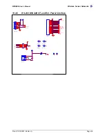
Page 42: ... AC ADC6 USART1_CLK AC PWM1B HIROSE PLUG J2 DF9 51P 1V 54 1 2 3 4 5 6 7 8 9 10 11 12 13 14 15 16 17 18 19 20 21 22 23 24 25 26 27 28 29 30 31 32 33 34 35 36 37 38 39 40 41 42 43 44 45 46 47 48 49 50 51 ADC5 USART1_RXD THRU2 PROG_MISO LED2 PW3 PW6 WR ADC3 RSTN PROG_MOSI INT 0 3 THERM_PWR PW7 PWM0 THRU2 INT 0 3 INT2 ADC2 UART_TXD0 PW0 THRU3 LED3 INT1 BAT_MON ADC7 PW4 PW5 THRU3 ADC1 LED1 USART1_CLK I...

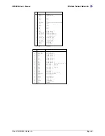
Page 43: ...5 POWER CONTROL 6 ADC INPUT 7 BATTERY MONITOR JTAG TDI ADC INPUT 6 JTAG TDO ADC INPUT 5 JTAG TMS ADC INPUT 4 JTAG TCK ADC INPUT 3 ADC INPUT 2 ADC INPUT 1 ADC INPUT 0 RSSI MONITOR TEMP SENSOR ENABLE THRU CONNECT 1 THRU CONNECT 2 THRU CONNECT3 RESET NEG GPIO PWM1B DIGITAL SUPPLY GROUND GROUND SENSOR SUPPLY GPIO GPIO GPIO GPIO BATTERY VOLTAGE MONITOR ENABLE LED3 LED2 LED1 GPIO GPIO GPIO POWER CONTROL...

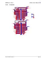
Page 44: ...32_RX TP6 J6 DB9 F RA 5 9 4 8 3 7 2 6 1 SPI_SCK ADC6 INT0 TP5 PWM1B TP7 PIN OUTER J7 PJ 014D 2 3 1 UART_TXD0 U1 LMS8117 3 3 3 1 2 4 VIN ADJ VOUT GND PW1 M3 MTG128 1 1 D1 B2100 C2 10uF 35V TDI TP9 TCK TDO TMS PW0 J5 DOT2 1 2 3 4 5 6 7 8 9 10 11 12 13 14 15 16 17 18 19 1 2 3 4 5 6 7 8 9 10 11 12 13 14 15 16 17 18 19 ADC4 ADC2 6310 0304 01 A MIB500CA MICA PROG BOARD CROSSBOW TECHNOLOGY INC B 2 3 Wedn...

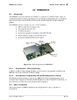
Page 45: ...er regulation and monitor and a q Power Over Ethernet POE power supply Figure 14 1 Photo of top side of an MIB600CA 14 1 1 Mote Network Ethernet Gateway A MICAz or MICA2 Mote running TOSBase or GenericBase is permanently installed on the MIB600 This forms a Mote RF to Ethernet bridge 14 1 2 Mote Network Programming and Out Band Diagnostic Channel The MICAz and MICA2 Motes connect to the MIB600 for...

Page 46: ...he SW2 in the POE position Power Over Ethernet IEEE802 3af POE M WARNING The Mote ground is at POE potential 48 V Do not connect MIB600 to facility building ground when using POE An IEEE 802 3af compliant power supply is provided for POE equipped facilities Ethernet appliance power 48 V is supplied at pins 4 5 and 7 8 of the 10 100 Base T RJ45 plug Refer to Appendix A for Base T wiring information...

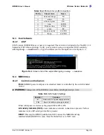
Page 47: ...ple below in Figure 14 3 Figure 14 3 Screen shot of the output after typing in uisp version 14 4 MIB600 Use 14 4 1 Controls and Indicators Power MIB600 power and power to attached mote is controlled by the switch labeled SW2 M WARNING Always turn off the MIB600 s power before installing removing a mote Table 14 5 SW2 Switch Settings Position Function 5V External 5V DC power supply selected POE Pow...

Page 48: ... of TOSBase GenericBase If other baud rates or communication parameters are used in your Mote application the serial server configuration must be changed 14 4 3 In System Programming The MIB600 ISP micro controller is attached to Port 10002 UISP assumes this port assignment by default Programming using MIB600 requires assigning an IP address to the device first followed by commands via Cygwin Inst...

Page 49: ...ernet 10Base T connection w IEEE 802 3af option J11 MOTE Umbilical Umbilical connection to Mote Adapter PCB Used for connection to MICA2 and MICA2DOT motes J12 JTAG MOTE JTAG connection to attached MICA2 MICA2DOT Mote Provides JTAG connectivity between external JTAG pod and Mote COM1 Factory use only Do not use INDICATORS D2 MOTE YELLOW Corresponds to attached Mote s Yellow LED D4 MOTE RED Corresp...

Page 50: ...MPR MIB User s Manual Wireless Sensor Networks Doc 7430 0021 06 Rev A Page 48 15 APPENDIX A 10 100 BASE T CABLING Category 5 e UTP color coding table ...

Page 51: ...rn unwanted product within thirty 30 days of Delivery Date Customer shall pay a twenty percent 20 restocking charge on any unwanted products returned to Crossbow No returns will be accepted after the thirty 30 day period has expired Where special equipment or services are involved Customer shall be responsible for all related work in progress however Crossbow shall take responsible steps to mitiga...

Page 52: ... around all sides of the equipment If the original shipping containers were discarded use heavy boxes with adequate padding and protection 16 3 4 Sealing the Container Seal the shipping container s with heavy tape or metal bands strong enough to handle the weight of the equipment and the container 16 3 5 Marking Please write the words FRAGILE DELICATE INSTRUMENT in several places on the outside of...

Page 53: ......

Page 54: ...Crossbow Technology Inc 41 Daggett Drive San Jose CA 95134 Phone 1 408 965 3300 Fax 1 408 324 4840 Email info xbow com ...

Reviews: