9
Description
T h e l e f t s i d e o f t h e S e n t r y
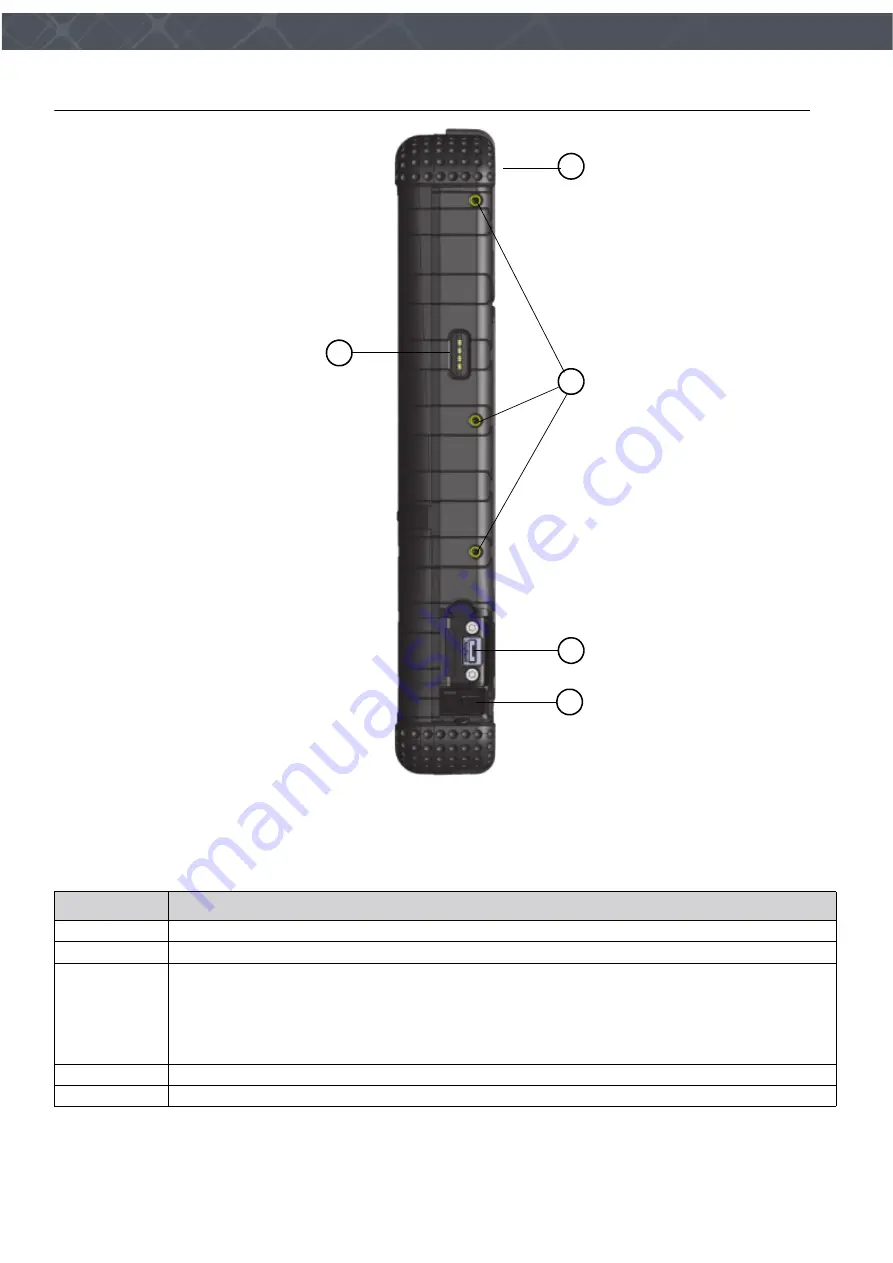
Figure 2
The left side of the Sentry
The following table describes the left side of the Sentry.
Table 7
The left side of the Sentry
Description
1
The top-end of the Verifier
®
Sentry.
2
The mounting points for accessories.
3
During normal operation, this port allows the Sentry to be a memory or camera device to a host
computer.
When the
On The Go (OTG) adapter
is used, the
USB connector
allows the Sentry to be a host
computer for an external USB device.
The connector can be a charge point.
When connected to a laptop, the connector is a device endpoint.
4
The attached cover for the USB connector is shown open.
5
This is the data connection for an accessory.
2
5
3
4
1
Summary of Contents for Verifier Sentry
Page 1: ...Verifier Sentry Operator Manual...
Page 2: ......
Page 3: ...Crossmatch Verifier Sentry Operator Manual...
Page 8: ...iv Verifier Sentry Operator Manual 870391 V1 1 Figures...
Page 10: ...vi Verifier Sentry Operator Manual 870391 V1 1 Tables...
Page 16: ...6 Verifier Sentry Operator Manual 870391 V1 1 Introduction Introduction...
Page 30: ...20 Verifier Sentry Operator Manual 870391 V1 1 Introduction Use the Sentry...


