background image

                                               8

8.

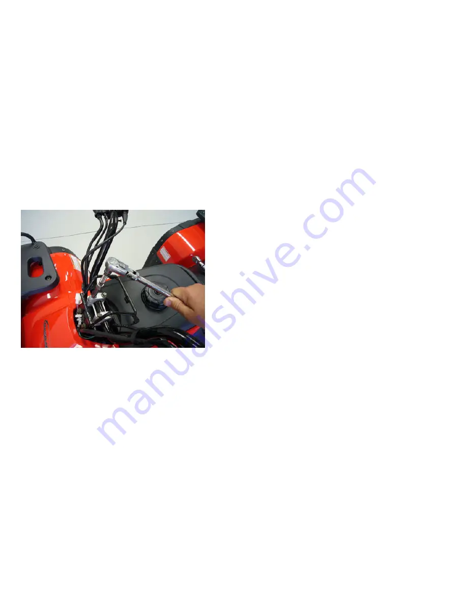
 Install handle bars with the bolts and hardware  provided.  See 

that  knurled  areas  on  handle  bars  are  evenly  spaced  between  the  two 
halves  of  the  pinch  mount  supports.  Lightly  snug  attaching  bolts  and 
position  handle  bars  at  the  desired  angle  best  suited  for  the  comfort 
and safety of the rider so that all hand controls are easily accessed and 
operated.  Turn  wheels  to  full  left  and  full  right  positions  to  assure 
adequate clearance for the rider’s legs and to check for binding cables 
or  wiring.  Finish  tightening  handle  bar  mounting  bolts  evenly  in  a 
criss-cross pattern and torque to 28 Ft/Lbs.

Step#08-fig#1-Handlebar installation

9.

Mount  the  shift  indicator  light  console,  if  so  equipped,  to  the 

bracket  on  top  of  the  handle  bar  mounting  with  the  bolts  supplied. 
Connect  the  wiring  harness  connectors  from  the  ATV  main  harness  to 
the connectors for the indicator lights. Make sure that  wiring colors of 
both halves are matched when connecting. NOTE: On some models it is 
possible to inadvertently switch two of the connectors because they are 
identical  and  will  interchange.  The  wiring  colors  must  be  matched  at 
the  time  you  connect  these  to  avoid  incorrect  information  from  being 
displayed on the light console.

Summary of Contents for All Terrain Vehicle 250

Page 1: ...e this bike REASSEMBLY MANUAL Note This ATV was fully assembled and tested at the CROSSRUNNER factory It was partially disassembled before shipping This manual gives specific instructions on how to fu...

Page 2: ...is ATV You will be referencing the Owner s Manual the battery service instructions and the tire pressure information sticker on the front fender as well as the Re assembly Manual during this procedure...

Page 3: ...t to scuff fenders or bumpers while removing This should not be attempted by one person alone Two people lifting together can remove the frame work without causing damage to the ATV or harm to themsel...

Page 4: ...se loss of control Use the valve core tool supplied with the ATV tool kit to tighten the valve core in each valve stem before attempting to add air Inflate the tires to seat the bead taking care not t...

Page 5: ...ned for the specific type wheel and ATV Evenly snug each lug nut by hand in a star pattern Final wheel torque must be done when ATV is sitting on flat ground DO NOT attempt to perform final wheel torq...

Page 6: ...emove bolts holding rear axle to frame base Note Packing methods may vary at times on some models Set parking brake for front wheels to prevent ATV from rolling off packing frame base Lift and support...

Page 7: ...d installing wheels carefully lower ATV release parking brake and roll off metal shipping frame onto flat level surface Reset the parking brake and perform the final wheel torque procedure Torque all...

Page 8: ...ightening handle bar mounting bolts evenly in a criss cross pattern and torque to 28 Ft Lbs Step 08 fig 1 Handlebar installation 9 Mount the shift indicator light console if so equipped to the bracket...

Page 9: ...9 Step 09 fig 1 Console wiring 10 Install rack bars on utility racks with the hardware provided Step 10 fig 1 Rack installation...

Page 10: ...e fuel line near any part of the exhaust or hot section of the engine and take care to tuck it in away from the rider s feet and legs so that it cannot be snagged Step 11 fig 1 Fuel line installation...

Page 11: ...tery and then test for proper voltage If the battery meets the voltage specs called for in the battery instructions when tested install in ATV The RED cables are positive and the GREEN cables are nega...

Page 12: ...t able to bind kink or be pinched Keep them at least 1 or more away from any contact with engine or exhaust Step 15 fig 1 Inspect hose routing 16 Inspect throttle brake and clutch cable free play adju...

Page 13: ...13 Step 16 fig 2 Front brake cable freeplay adjustment Step 16 fig 3 Rear brake cable free play adjustment...

Page 14: ...14 Step 16 fig 4 Front brake adjustment Step 16 fig 5 Rear brake adjustment...

Page 15: ...tion when selected This is tested with key on engine off Next inspect headlight and brake light operation 19 Add fuel turn fuel valve to ON position and inspect for leaks Install gas cap on fuel tank...

Page 16: ...After ATV is started closely inspect for any fuel or oil leaks Confirm parking brake holds adequately and test each gear selection for proper indication on center console Copyright North American Impo...

Reviews: