background image

Copyright © 2019 by Midwest Air LLC 


DA20 C1 Eclipse  

Training Manual  


Summary of Contents for DA20 C1 Eclipse

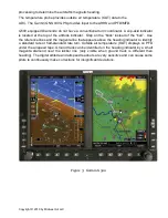
Page 1: ...Copyright 2019 by Midwest Air LLC DA20 C1 Eclipse Training Manual...

Page 2: ...During Taxi 9 3 4 Pre Takeoff Briefing 9 4 Takeoff Procedures 11 4 1 Normal Takeoff Flaps T O 11 4 2 Short Field Takeoff Flaps T O 12 4 3 Soft Field Takeoff Flaps T O 13 5 Landing Procedures 14 5 1 V...

Page 3: ...ectrical system and each other and utilize impulse coupling C Continental IO 240 B H Horizontally Opposed 4 cylinder A Air Cooled N Normally Aspirated D Direct Drive 1 2 Oil The acceptable range for o...

Page 4: ...ng brake is released 1 6 Flaps The DA20 C1 is equipped with Electric Plain flaps with 3 positions 0 Take off Landing controlled by a three position flap operating switch on the instrument panel The el...

Page 5: ...ered to the engine s mechanical fuel pump by the fuel supply line Fuel is metered by the fuel control unit The DA20 C1 is equipped with a DUKES constant flow vane type two speed and electric fuel pump...

Page 6: ...emaining power source is the battery 20 amps for 30 minutes 1 11 Ignition System The engine is provided with two independent ignition systems The two engine driven magnetos are independent from the po...

Page 7: ...the brick instead of the ball Use the reference lines and the magenta line that appears above the heading indicator to identify a standard rate or half standard rate turn Outside air temperature OAT...

Page 8: ...in landing position VNO Maximum Structural Cruising Speed 118 Do not exceed this speed except in smooth air and then only with caution VNE Never Exceed Speed 164 Do not exceed this speed in any operat...

Page 9: ...aximum Ramp Weight 1770 lbs 803 kg Maximum Takeoff Weight 1764 lbs 800 kg Maximum Landing Weight 1764 lbs 800 kg Maximum Weight in Baggage Compartment 44 lbs 20 kg Weight of 100LL Per Gallon 6 lbs Wei...

Page 10: ...rees in 5 minutes Altimeters set crosscheck current baro setting within 75 feet of field elevation VSI reading zero up to 100 deviations are approved but must be taken into account during flight Turn...

Page 11: ...runway remaining for a complete stop Throttle immediately closed Land straight ahead brake as required Engine failure after rotation with no runway remaining Maintain control pitch for best glide Onl...

Page 12: ...s T O 2 Line up on centerline positioning controls for wind 3 Smoothly apply full power 4 Check engine gauges 5 Right rudder as required for turning tendencies 6 Airspeed Alive 7 Start slow rotation a...

Page 13: ...terline positioning controls for wind 3 Hold brakes 4 Smoothly apply full power 5 Check engine gauges 6 Release brakes 7 Airspeed Alive 8 Briskly rotate at 51 KIAS 9 Accelerate to 57 KIAS VX 10 When c...

Page 14: ...full power holding full AFT on the stick check engine gauges 4 As nose lifts off ease back pressure keep nose wheel off the ground 5 Lift off at the lowest possible airspeed remain in ground effect 6...

Page 15: ...lide path towards a predetermined point on the landing runway It is based on the pilot s judgment of certain visual cues and depends on a constant final descent airspeed and configuration FAA H 8083 3...

Page 16: ...shed TPA typically 1 000 AGL 4 Complete the VFR Landing Brief when established on the downwind 5 When abeam touchdown point or on extended base or on extended final when ready to descend out of patter...

Page 17: ...t when established on the downwind 5 When abeam touchdown point or on extended base or on extended final when ready to descend out of pattern altitude Reduce power to 1500 RPM and select Flaps T O 6 D...

Page 18: ...Copyright 2019 by Midwest Air LLC 5 5 Soft Field Landing Flaps LDG...

Page 19: ...Brief when established on the downwind 5 When abeam touchdown point or on extended base or on extended final when ready to descend out of pattern altitude Reduce power to 1500 RPM and select Flaps T...

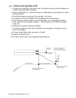
Page 20: ...Copyright 2019 by Midwest Air LLC 5 6 Power Off 180 Procedure...

Page 21: ...typically 1 000 AGL 4 Complete the VFR Landing Brief when established on the downwind 5 When abeam touchdown point or on extended base or on extended final when ready to descend out of pattern altitud...

Page 22: ...HDG 10 Speed 10kts NOTE Minimum safe altitude for this maneuver is 1 500 AGL Establish cruise configuration and complete the pre maneuver check 1 Perform clearing turns 2 Set power to 2000 RPM 3 Star...

Page 23: ...allooning tendency increase forward elevator as necessary to maintain altitude 7 Flaps LDG 8 Trim to relieve control pressures 9 Maintain altitude and heading 10 Slow to an airspeed that is 5 to 10 kn...

Page 24: ...imes 9 Recognize and announce symptoms of approaching stall 10 Sight sound feel 11 Stall warning horn activates 12 Aerodynamic buffeting Recovery procedure 1 Reduce the Angle of Attack AOA 2 Release e...

Page 25: ...to the horizon 9 maintain pitch by applying constant back pressure 10 Maintain coordination at all times 11 Recognize and announce symptoms of approaching stall 12 Sight sound feel 13 Stall warning h...

Page 26: ...f 90 KIAS 2 Maneuver is performed 1 000 AGL 3 Enter the maneuver 45 to the downwind with the first circuit to the left Downwind 1 Roll wings level parallel to the boundary 2 Maintain distance about 1...

Page 27: ...nd 1 Roll out wings level crabbing away from the boundary 2 Manage crab angle to maintain 1 2 mile distance from boundary 3 At field boundary edge turn downwind 4 Start with moderate bank 5 Increase b...

Page 28: ...r the area of other aircraft 5 Trim the airplane for level flight 6 First turn to the left at the highest ground speed and steepest bank angle max 45 degrees 7 Bank angle will gradually need to be dec...

Page 29: ...speed and steepest bank angle not to exceed 30 degrees 8 Directly crosswind moderate bank angle and decrease as the airplane turns upwind 9 Maintain coordinated flight throughout 10 Cross the line fe...

Page 30: ...a 90 degree reference point off your wing tip 4 Roll into a 30 degree bank 5 After the bank is established smoothly and continuously increase the pitch and simultaneously add climb power so as to arri...

Page 31: ...a bank so as to arrive at the 45 degree point with maximum pitch up and 15 degrees of bank 5 Passing the 45 degree point increase the bank and decrease the pitch so as to arrive at the 90 degree point...

Page 32: ...r so as to reach the abeam point at best glide speed 73 KIAS 6 Abeam the reference point roll into a bank 45degrees 7 Begin a constant radius turn around a point compensating for wind drift by continu...

Page 33: ...Copyright 2019 by Midwest Air LLC Eights On Pylons Maneuver...

Page 34: ...grees to downwind 4 When the pylon passes below the wing smoothly roll into a turn using coordinated aileron and rudder so that the pylon maintains a constant position relative to the wingtip 5 As the...

Page 35: ...ires a minimum altitude of 3 500 AGL 1 Clearing Turns 2 Clean configuration 3 Mixture forward 4 Fuel pump on 5 Throttle idle 6 Maintain 73 KIAS 7 Establish a 45 degree bank 8 Immediately pull back har...

Reviews: