Vortex FP Compact Installation & Operation Manual
5
Issue 1, January 2013
cable. Other cables types may be used provided suitably certified cable glands are also
used.
Important note:
If a Vortex FP Compact system is to be connected to a control system in a
safe area (ie control room, plant room etc) it is strongly recommended that the Vortex RS-
485 function terminals are connected to an accessible point in the safe area. All Vortex
configurations, calibration and diagnostic functions can then be carried-out using the Vortex
PC software supplied with the system from the safe area without requiring the Flameproof
junction box to be opened. Refer to the Vortex manual for more details.
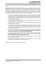
1. The fixing brackets/bolts are supplied with, but not fitted to the Vortex FP Compact
enclosure. To fit the brackets lay the Vortex FP Compact enclosure on a suitable
surface and raise onto one end. Remove the lid retaining bolts and carefully open the
lid of the enclosure. The fixing brackets should be secured to the enclosure using the
supplied retaining bolts/nuts.
Once the brackets are attached, close the door and restrain using one fixing bolt
before attempting to mount the cabinet.
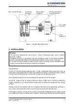
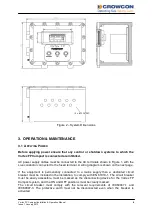
2. Lift the system in to place and secure via the mounting bracket fixing points shown in
the diagram on the next page.
3. Ten M20 entries are provided for field cables. Connect the cables to the system
using certified Exd cable glands. Certified M20 plugs are fitted to five entries and can
be removed if necessary for additional cables. All spare cable entries must have Exd
certified plugs securely fitted.
4. Cable conductors should be connected to the Vortex modules and terminals as
shown in the Vortex manual (M07211).
Warning: power must not be applied until
the enclosure lid has been closed and securely tightened.
5. I.S. field devices (gas detectors and/or alarms) must be connected via safety barriers
mounted externally from the system, in accordance with their instructions.
Zener
Barriers must be grounded to a dedicated I.S. earth.
6. Once all cable connections have been made the lid should be closed and tightly
secured using the fixing bolts.
7. Connections to field devices (gas detectors, fire detectors etc) must be made
according to the instructions provided with each device.
System dimensions are shown on the following page.


