background image

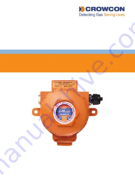
Installation, Operation and Maintenance Instructions

M077910

Issue 4 

March 2020

Xsafe Bright

Gas Detectors with Display and Relays

Summary of Contents for Xsafe Bright

Page 1: ...Installation Operation and Maintenance Instructions M077910 Issue 4 March 2020 Xsafe Bright Gas Detectors with Display and Relays...

Page 2: ......

Page 3: ...ng Requirement 4 to 20 mA Current Loop 7 2 6 Cabling Requirement Multidrop MODBUS 8 2 6 1 Calculating acceptable cable length and detector quantities 9 2 7 Earthing requirements 12 2 8 Cable glands 12...

Page 4: ...4 Specifications 24 5 Spare parts 25 6 Warranty 26 Appendix 28...

Page 5: ...ormation Safety information relevant to Ex requirements The cable gland must be installed before use and must have an appropriate ingress protection for the application and environment Unused cable en...

Page 6: ...the detector to rise above its specified limits and cause premature failure A sunshade is available for Xsafe Bright 1 3 Storage instructions Some types of sensor available with Xsafe Bright have limi...

Page 7: ...Introduction 3 English 1 5 Product dimensions All dimensions in millimetres Diagram 1 Xsafe Bright dimension view...

Page 8: ...Introduction 4 English 1 6 Exploded view Diagram 2 Xsafe Bright exploded view...

Page 9: ...unted outdoors Crowcon recommend the use of a Spray Deflector Part No C01052 Consider ease of access for functional testing and servicing Consider how the escaping gas may behave due to natural or for...

Page 10: ...ices to the multi drop communications Note Please avoid direct water jets into the sensors as it is likely to lead to damage 2 3 Internal Electrical Connections Diagram 3 Xsafe Bright internal electri...

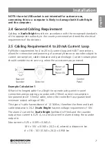
Page 11: ...Current consumption should consider worst case e g when the accessories are powered Example Calculation 1 What is the longest cable for a Bright to operate using point to point connection and powerin...

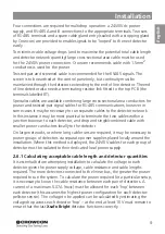
Page 12: ...ximum cable distances given typical cable parameters for this example calculation C S A Resistance Ohms per km Max Distance km mm2 Awg Cable Loop 1 0 17 18 1 36 2 2 2 1 5 15 12 1 24 2 3 3 2 5 13 7 4 1...

Page 13: ...ector network In this instance it may be most practical to terminate the two cables within a junction box near to each detector and drop and single combined cable with smaller power conductors locally...

Page 14: ...070A to the value for the aggregate current to get to 0 14A the minimum current running through the last but one hop of the bus Multiply this by the cable resistance for the last but one hop to get t...

Page 15: ...gment V n 3 10 03388 0 06776 10 10164 V Tabulating the results for each detector position we get Detector Voltage at Detector V Cable current A Cable voltage drop V N 1 10 0 070 0 03388 N 2 10 03388 0...

Page 16: ...rminals are provided on the outside of the Xsafe Bright enclosure adjacent to the top right cable entry and internally adjacent to the left hand sounder out cable connector 2 8 Cable glands Instructio...

Page 17: ...d cable 1 Backnut 2 Compression Spigot 3 Compression seal 4 Middle Nut 5 Reversible Armour Clamping Ring 6 Armour Spigot 7 Inner seal 8 Entry 1 Expose the armour braid A by stripping the cable s armou...

Page 18: ...braid has been successfully clamped between the Armour Spigot and the Armour Clamping Ring If armour braid not clamped repeat assembly 6 Remove Entry and refit Inner Seal replace Entry and re assemble...

Page 19: ...r product code C01052 For outdoor installations and sensor protection from water sprays Weatherproof cap product code C01442 For use offshore or very wet environments Flow adaptor product code C01339...

Page 20: ...s on a black background and can be viewed clearly even in bright sunlight Reversed white screen saver will be activated in normal detection condition while long time no operation Diagram 4 Xsafe Brigh...

Page 21: ...n normal operation the gas level will be indicated on the display Use the supplied magnetic wand to select the Scroll key to move between the information screens shown below Diagram 6 Gas status scree...

Page 22: ...en 4 Set Alarm 1 to adjust the first alarm threshold 5 Set Alarm 2 to adjust the second alarm threshold Note When Alarm 2 threshold is set lower than the Alarm 1 threshold both alarms are falling e g...

Page 23: ...ill be displayed When zeroing is complete a pass or fail screen will be displayed Press OK to return to the Main menu Note Calibration of oxygen channels Zeroing is not required for an oxygen instrume...

Page 24: ...ot use damaged components or damaged electrochemical cells The sinter should be inspected regularly and replaced if it has become contaminated A blocked sinter may prevent gas from reaching the sensor...

Page 25: ...e sensor Ensure the grub screw is re secured 6 Zero and calibrate the new sensor Warning Xsafe Bright sensor modules are NOT compatible with Xgard or Xsafe sensor Modules 3 9 IR Carbon Dioxide It is u...

Page 26: ...f the sensor has dropped 3 11 Maintenance and cleaning of the PID sensor For cleaning and maintenance of the PID please refer to Crowcon Application Note PID AN 001 Discarding the PID electrode stack...

Page 27: ...re flush 3 Refit the sensor into the sensing equipment 4 Re calibrate the gas detector in accordance with manufacturer s instructions Ordering spare components Quote the order code below 10 6eV lamp f...

Page 28: ...output 4 20mA current sink or source RS 485 Modbus RTU HART optional Relays Alarm 1 Alarm 2 Fault SPDT contacts rated 1A 24Vdc Sounder Out MOSFET open collector drive 24Vdc nominally 0 7A maximum loa...

Page 29: ...equire 7 M03810 Xgard Bright M3x6 Grub Screw Customer may require 2 M02125 Xgard Bright Spare M20 to 1 2 NPT Adapter C03756 Xgard Bright Cro Mag MIS99033 Xgard Bright Allen Key S015132 S XGB Spare Sen...

Page 30: ...lication It is the clients sole responsibility to carry out the necessary tests to evaluate the usefulness of the products and review all applicable regulations and standards to ensure their safety of...

Page 31: ...27 English Our postal address is Crowcon Detection Instruments Ltd UK Head Office 172 Brook Drive Milton Park Oxfordshire OX14 4SD...

Page 32: ...12O 10 2 6 Aniline C6H7N 7 7 0 5 Anisole C7H8O 8 21 0 59 Asphalt petroleum fumes 9 1 Benzaldehyde C7H6O 9 49 0 7 Benzene C6H6 9 24 0 5 Benzene thiol C6H5SH 8 32 0 7 Benzonitrile C7H5N 9 62 0 7 Benzyl...

Page 33: ...o 1 3 butadiene 2 C4H5Cl 8 79 3 2 Chlorobenzene C6H5Cl 9 07 0 45 Chloroethyl methyl ether 2 C3H7ClO 9 2 6 Chlorotoluene o C7H7Cl 8 83 0 5 Chlorotoluene p C7H7Cl 8 69 0 4 Cresol m C7H8O 8 36 2 2 Cresol...

Page 34: ...C4H11N 8 01 1 4 Diethylaminopropylamine 3 C7H18N2 9 5 Diisobutylene C8H16 8 91 0 7 Diisopropyl ether C6H14O 9 2 0 92 Diisopropylamine C6H15N 7 73 0 7 Diketene C4H4O2 9 6 2 2 Dimethoxymethane C3H8O2 9...

Page 35: ...4O2 9 21 0 8 Furfuryl alcohol C5H6O2 9 9 2 Gasoline 9 9 0 9 Glutaraldehyde C5H8O2 9 6 0 9 Heptan 2 one C7H14O 9 33 0 85 Heptan 3 one C7H14O 9 02 0 73 Heptane n C7H16 9 92 2 2 Hexan 2 one C6H12O 9 34 0...

Page 36: ...0 8 Isopropanol C3H8O 10 17 4 Isopropyl acetate C5H10O2 9 99 2 2 Isopropyl chloroformate C4H7O2Cl 10 2 1 6 Jet Fuel JP 4 9 0 8 Jet Fuel JP 5 9 0 7 Jet Fuel JP 8 9 0 7 Kerosene 8 0 8 Ketene C2H2O 9 62...

Page 37: ...hacrylate C5H8O2 9 7 1 31 Methyl propyl ketone C5H10O 9 39 0 79 Methyl sulphide C2H6S 8 69 0 8 Methyl tert butyl ether C5H12O 9 24 1 Methyl 2 propen 1 ol 2 C4H8O 9 24 1 3 Methyl 2 pyrrolidinone N C5H9...

Page 38: ...5NO2 9 92 1 7 Nitrogen trichloride NCl3 10 22 1 Nonane n C9H20 9 72 1 4 Octane n C8H18 9 8 1 6 Octene 1 C8H16 9 43 0 7 Pentan 2 one C5H10O 9 38 0 99 Pentan 3 one C5H10O 9 31 0 77 Pentandione 2 4 C5H8O...

Page 39: ...bromoethane 1 1 2 2 C2H2Br4 10 2 Toluene C7H8 8 82 0 56 Toluene 2 4 diisocyanate C9H6N2O2 8 82 1 6 Trichloroethylene C2HCl3 9 45 0 6 Trimethylbenzene mixtures C9H12 8 41 0 4 Turpentine C10H16 8 0 6 Un...

Page 40: ...truments Ltd Vlambloem 129 3068JG Rotterdam Netherlands Tel 31 10 421 1232 Fax 31 10 421 0542 Email eu crowcon com Website www crowcon com Singapore Office Crowcon Detection Instruments Ltd Block 194...

Reviews: