background image

1

Series 16H


Gas-Fired Natural Draft Hot Water Boilers


INSTALLATION INSTRUCTIONS

 These instructions must be affixed on or adjacent to the boiler

Models:

• 

16H-340

• 

16H-410  

• 

16H-460

• 

16H-505

WARNING

: Improper installation, 

adjustment, alteration, service or 

maintenance can cause property 

damage, injury, or loss of life. 

For assistance or additional 

information, consult a qualified 

installer, service agency  or  

the gas supplier. Read these 

instructions carefully before 

installing.

D

E S I G N E D   T O  

L

E A D

Manufacturer of Hydronic Heating Products

P.O. Box 14818  3633 I. Street

Philadelphia, PA  19134

www.crownboiler.com

3050579

Summary of Contents for 16H-340

Page 1: ...llation adjustment alteration service or maintenance can cause property damage injury or loss of life For assistance or additional information consult a qualified installer service agency or the gas supplier Read these instructions carefully before installing D E S I G N E D T O L E A D Manufacturer of Hydronic Heating Products P O Box 14818 3633 I Street Philadelphia PA 19134 www crownboiler com ...

Page 2: ... appliance If you smell gas vapors DO NOT try to operate any appliance DO NOT touch any electrical switch or use any phone in the building Immediately call the gas supplier from a remotely located phone Follow the gas supplier s instructions or if the supplier is unavailable contact the fire department DO NOT install this boiler on combustible flooring carpet concrete over combustible flooring or ...

Page 3: ...disconnect any components of this boiler without positively assuring the water is cool and has no pressure Always wear protective clothing and equipment when installing starting up or servicing this boiler to prevent scald injuries Do not rely on the pressure and temperature gauges to determine the temperature and pressure of the boiler This boiler contains components which become very hot when th...

Page 4: ... Pre Installation 6 II Boiler Assembly 8 III Gas Control System Assembly 15 IV Water Trim and Piping 19 V Gas Piping 23 VI Venting 25 VII Electrical 28 VIII System Start up 36 IX Service Troubleshooting 42 X Repair Parts 49 ...

Page 5: ...lons Approx Shipping Weight LB A B C D E Knockdown 16H 340 27 1 2 13 3 4 8 27 13 16 18 8 dia x 15 ft 15 9 870 16H 410 31 1 4 15 5 8 9 30 13 16 20 8 dia x 15 ft 17 9 955 16H 460 35 17 1 2 10 33 1 2 22 10 dia x 15 ft 19 9 1050 16H 505 38 3 4 19 3 8 10 33 1 2 22 10 dia x 15 ft 21 9 1150 Table 1 Dimensional Data ...

Page 6: ...ue connector 6 D Provide clearance for servicing and proper operation following clearances are recommended and may be reduced to minimum clearances shown above 1 Single boiler 16H 340 Front 24 61 0 cm 2 Single boiler 16H 410 16H 505 Front 48 122 0 cm 3 Multiple modular boiler Sides 1 2 5 cm E Install boiler on level floor as close to chimney as possible For basement installation provide a solid ba...

Page 7: ...llowing i Minimum free area of 1 square inch per 3 000 Btu per hour input of all equipment in space ii Free area shall not be less than the sum of the areas of all vent connectors in the confined space Alternate method for boiler located within confined space Use indoor air if two permanent openings communicate directly with additional space s of sufficient volume such that combined volume of all ...

Page 8: ... rear corner of Base End Panel raise boiler and install 1 wood blocks under rear corners Install pipe roller between Base and skid 3 Remove 1 wood blocks Place 3 pipe roller on floor behind skid 4 Roll boiler off skid Move skid out of way 5 Roll boiler until 3 roller is located as shown Use pry bar to install wood blocks under front corners of base Remove 3 roller Figure 2 Skid Removal Tapping Siz...

Page 9: ...ure 4 Installation of Special Base for Combustible Flooring gauge pressure 6 Examine boiler for leaks or damage due to shipment or handling 7 Remove plugs from Return Tapping B Tapping C and Tapping E if second limit or operating control is used Also remove fill valve and piping purge valve and piping and pressure gauge E Install special base if installation is on combustible flooring See Figure 4...

Page 10: ...mbly using 20 x 1 carriage bolts washers and nuts 2 Seal between top of Base Front Panel and Section Assembly with furnace cement shipped in Combination Boiler Parts and Control Carton 3 Seal between top of Base Rear Panel and Section Assembly with furnace cement K Install Pilot Main Burner Assembly See Figure 7 Assembly is located in Combination Boiler Parts and Control Carton Verify assembly is ...

Page 11: ...11 Figure 6 Flame Roll out Switch Installation Figure 7 Burner Burner Access Panel Installation ...

Page 12: ... RATING LABEL ENCLOSED Remove Combustible Clearance Label from Combination Boiler Parts and Controls Carton Attach to Vestibule Panel in locations shown 6 Attach Vestibule Panel to Left Side and Right Side Panels 7 Attach Lower Front Tie Bar to Left Side and Right Side Panels 8 Engage Upper Front Panel in slots on Left Side and Right Side Panels Place Top Panel in position Attach Top Panel to Left...

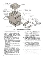
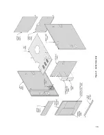
Page 13: ...13 Figure 8 Jacket Assembly ...

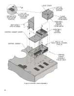
Page 14: ...14 Figure 9 EP CSD 1 Control Installation ...

Page 15: ... for connection details 4 Mount Transformer continuous circulation or Control Center intermittent circulation to Junction Box See Figure 8 a Canada only loop 4 nylon cable tie between junction box and transformer control center b Attach transformer control center to junction box B EP CSD 1 Control System Install Gas Control System All components are located in Combination Boiler Parts and Control ...

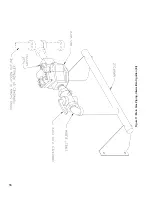
Page 16: ...16 Figure 11 Main Gas Piping Intermittent Ignition EI ...

Page 17: ...17 Figure 12 Schematic Pilot Piping Honeywell EI USA ...

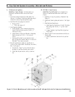
Page 18: ...18 Figure 15 Schematic Gas Piping EP CSD 1 Control System 16H 410 16H 505 ...

Page 19: ... discharge piping must be piped such that the potential of severe burns is eliminated DO NOT pipe in any area where freezing could occur DO NOT install any shut off valves plugs or caps Consult Local Codes for proper discharge piping arrangement C Install Safety Relief Valve See Figure 16 Components are located in Water Trim Carton Safety Relief Valve must be installed with spindle in vertical pos...

Page 20: ...iping See Figure 19 a Install 2 NPT x 10 Nipple into Supply Tapping A See Figure 3 Figure 18 Temperature Pressure Gauge Installation Figure 19 Alternate Temperature Pressure Gauge Installation b Install 2 NPT x NPT x 2 NPT Tee provided or 2 NPT x 2 NPT x NPT Tee installer furnished NPT leg should face forward c Install NPT x NPT Bushing d Insert Temperature Pressure Gauge Tighten by applying press...

Page 21: ...liability Crown recommends maintaining temperature differential drop across the system at 40 F or less and return water temperature at minimum of 135 F Continued boiler operation for prolonged periods of time under conditions when temperature differential across the system exceeds 40 F and or return water temperature stays below 135 F may result in premature boiler failure due to flue gas condensa...

Page 22: ...st be provided with a low water cutoff device as part of installation 5 A start up strainer is recommended for all installations new and replacement alike to prevent system debris and sediment from ending up in the boilers where it will inhibit heat transfer and may eventually cause a cast iron section to crack from overheating G Water Heater if used Refer to Mega Stor Installation and Operating I...

Page 23: ...factor be applied For specific gravity greater than 0 70 apply gravity factor from Table 8 If exact specific gravity is not shown choose next higher value For materials or conditions other than those listed above refer to the National Fuel Gas Code NFPA 54 ANSI Z223 1 or size system using standard engineering methods acceptable to authority having jurisdiction WARNING Failure to use proper thread ...

Page 24: ...0 78 1 0 3 1 0 824 0 44 23 1 11 5 5 3 2 1 0 97 1 4 4 1 1 1 049 0 56 29 4 14 7 6 8 2 6 1 23 1 8 5 3 1 1 380 0 74 38 6 19 3 8 9 3 5 1 6 2 3 6 9 Specific Gravity Correction Factor Specific Gravity Correction Factor 0 50 1 10 1 30 1 07 0 55 1 04 1 40 1 04 0 60 1 00 1 50 1 00 0 65 0 96 1 60 0 97 0 70 0 93 1 70 0 94 0 75 0 90 0 80 0 87 Table 8 Specific Gravity Correction Factors WARNING Do not use match...

Page 25: ...e lining will cause severe injury or death C Install Draft Hood on canopy outlet Maintain height from Jacket Top Panel to Draft Hood skirt as shown in Figure 1 DO NOT ALTER CUT OR MODIFY DRAFT HOOD WARNING Do not alter boiler draft hood or place any obstruction or non approved damper in the breeching or vent system Flue gas spillage can occur Unsafe boiler operation will occur D Install Blocked Ve...

Page 26: ...nstallation 2 Where two or more appliances vent into a common vent the area of the common vent should at least equal the area of the largest vent plus 50 of the area of the additional vents Do not connect the vent of this appliance into any portion of mechanical draft system operating under positive pressure 3 Vent connector should have the greatest possible initial rise above the draft hood consi...

Page 27: ...common venting system are located and other spaces of the building Turn on clothes dryers and any appliance not connected to the common venting system Turn on any exhaust fans such as range hoods and bathroom exhausts so they will operate at maximum speed Do not operate a summer exhaust fan Close fireplace dampers 4 Place in operation the appliance being inspected Follow the Lighting or Operating ...

Page 28: ...0 and connect wiring as shown on the appropriate wiring diagram 2 Connect supply wiring and electrically ground boiler in accordance with requirements of authority having jurisdiction or in absence of such requirements the National Electrical Code ANSI NFPA 70 B Wire Vent Damper if used optional on 16H 340 thru 16H 505 See Figure 24 1 Attach Vent Damper Harness to mounting hole in JacketLeftSidePa...

Page 29: ...nergized 5 When the call for heat is satisfied the damper relay coil is de energized closing contacts which energize the damper motor This causes the damper to close When the damper blade reaches the fully closed position the damper motor is de energized POWER FAILURE The damper blade will stop in the position it was in when power failed Combustion can never take place unless the damper blade is i...

Page 30: ... call for heat Vent Damper if used closes Normal operation resumes when water temperature falls below set point ii Blocked Vent Switch Automatically interrupts main burner operation when excessive flue gas spillage occurs Circulator continues to operate and Vent Damper if used remains open with call for heat If blocked vent switch is activated do not attempt to place boiler in operation Correct ca...

Page 31: ...31 Figure 31 Wiring Diagram Honeywell EI USA Intermittent Circulation 16H 340 16H 510 MegaStor Relay MegaStor ...

Page 32: ...culator continues to operate with call for heat Normal operation resumes when water temperature falls below set point ii Blocked Vent Switch Automatically interrupts main burner operation when excessive flue gas spillage occurs Circulator continues to operate with call for heat If blocked vent switch is activated do not attempt to place boiler in operation Correct cause of spillage and reset block...

Page 33: ...33 Figure 35 Wiring Diagram EP Ignition System Natural Gas Only Intermittent Circulation EP CSD 1 Natural Gas USA Only 16H 410 16H 505 ...

Page 34: ...cDonnell Miller 751P MT 120V L W C O Wiring for Boilers with 24V Limit Circuits EI 16H 340 16H 505 Figure 37 McDonnell Miller 751P MT 120V L W C O Wiring for Boilers with 120V Limit Circuits EP CSD 1 16H 410 16H 505 ...

Page 35: ...vel OEM 170 550 650 750 120V L W C O Wiring for Boilers with 24V Limit Circuits EI 16H 340 16H 505 Figure 39 Hydrolevel OEM 170 550 650 750 120V L W C O Wiring for Boilers with 120V Limit Circuits EP CSD 1 16H 410 16H 505 ...

Page 36: ...pansion tank 7 Allow water to overflow from bucket until discharge from hose is bubble free for 30 seconds 8 Close the open zone valve or shut off valve for the zone being purged of air then open the zone valve or shut off valve for the next zone to be purged Repeat this step until all zones have been purged At completion open all zone valves or shut off valves VIII System Start Up 9 Close purge v...

Page 37: ...37 Figure 41 Operating Instructions EI ...

Page 38: ...se instructions exactly a fire or explosion may result for gas including near the floor If you smell gas STOP Follow B in the safety information above on this label If you do not smell gas go to the next step 14 EP SYSTEM See control location diagram On the electronic control 5 Close manual pilot valve CSD 1 Boilers Only 4 EP SYSTEM Flip both rocker switches to O position off 5 This appliance is e...

Page 39: ... will also affect primary air injection Adjust primary air as follows Figure 45 Honeywell Q3481B Pilot Flame 24V Electronic Ignition Figure 46 Honeywell Q179C Pilot Flame EP Figure 47 Main Burner Flame CAUTION Avoid operating this boiler in an environment where saw dust loose insulation fibers dry wall dust etc are present If boiler is operated under these conditions the burner interior and ports ...

Page 40: ...ust gas input rate will result in over firing or under firing of the appliance Improper and unsafe boiler operation may result 5 Compare measured input rate to input rate stated on rating label a Boiler must not be overfired Reduce input rate by decreasing manifold pressure Do not reduce more than 0 3 inch w c If boiler is still overfired contact your Crown distributor or Regional Office for repla...

Page 41: ... environmental regulations P Check Damper Operation If boiler is equipped with vent damper vent damper must be in open position when boiler main burners are operating Start boiler refer to instructions on damper to determine if damper is in full open position Q Install Front Removable Panel 1 Engage top flange longer of 2 flanges behind Upper Front Panel 2 Swing lower portion of door toward boiler...

Page 42: ...nt accessories due to condensation or other reasons 4 proper support no sags particularly in horizontal runs 5 tightness of joints Remove all accumulations of soot with wire brush and vacuum Remove all obstructions Replace all deteriorated parts and support properly Seal all joints D Remove Main Burners for cleaning changing orifice plugs or repairs 1 Shut down gas boiler in accordance with Lighti...

Page 43: ... Long sleeved loose fitting clothing 3 Gloves 4 Eye Protection Take steps to assure adequate ventilation Wash all exposed body areas gently with soap and water after contact Wash work clothes separately from other laundry and rinse washing machine after use to avoid contaminating other clothes Discard used RCF components by sealing in an airtight plastic bag RCF and crystalline silica are not clas...

Page 44: ...lot Bracket is in proper location See Table 13 H Lubrication Manufacturers Instruction should be followed on all parts installed on boiler requiring lubrication This includes type of lubricant to be used frequency of lubrication and points to lubricate I Check operation Refer to Section VIII System Start up Boiler Model Pilot Located Between Burners 16H 340 6 7 16H 410 6 7 16H 460 7 8 16H 505 8 9 ...

Page 45: ...m may not operate reliably over time Service call recommended Note This indication may flash temporarily during or shortly after lightoff on some applications Check gas supply pilot burner flame sense wiring contamination of flame rod burner ground connection OFF No Flame or Flame Signal below minimum threshold for system operation N A a Flash Code Descriptions Heartbeat Constant second bright sec...

Page 46: ...trol remains in wait mode When the fault corrects control resumes normal operation after one minute delay Check transformer and AC line for proper input voltage to the control Check with full system load on the transformer 6 2 5 minute Retry Delay On every third retry on same Call for Heat Initiate new trial for ignition after retry delay completed Check gas supply pilot burner spark and flame sen...

Page 47: ...47 Honeywell EI Trouble Shooting Guide ...

Page 48: ...48 THIS PAGE LEFT BLANK INTENTIONALLY ...

Page 49: ...rown wholesale distributor Should you require assistance in locating a Crown distributor in your area or have questions regarding the availability of Crown products or repair parts please contact Crown Customer Service at 215 535 8900 or Fax 215 535 9736 X Repair Parts ...

Page 50: ...71608 1 6171609 1 6171610 1 1A Left End Section 7171601 1 1 1 1 1B Intermediate Section 7171603 5 6 7 8 1C Right End Section 7171602 1 1 1 1 1D Tie Rod 80861013 1 80861034 1 80861035 1 80861036 1 1E Washer Procure Locally 4 4 4 4 1F Nut Procure Locally 4 4 4 4 1G Slip Nipple 3 Upper Lower 7066002 12 14 16 18 1H Flue Baffle 7111623 6 7 8 9 ...

Page 51: ...t No Quantity 16H 340 16H 410 16H 460 16H 505 2 Canopy 2A Canopy 61116071 1 260128 1 61116091 1 61116110 1 2B Bolt Carriage 20 x 1 Procure Locally 2 2 2 2 2C Washer Flat Procure Locally 2 2 2 2 2D Nut 20 Procure Locally 2 2 2 2 ...

Page 52: ...0627 1 260628 2 260629 2 260630 2 3F Jacket Attachment Bracket 7041601 4 4 4 4 3G Bolt Carriage 20 x 1 Procure Locally 4 4 4 4 3H Washer Flat Procure Locally 4 4 4 4 3J Nut 20 Procure Locally 4 4 4 4 3K Screw Self Tapping 20 x Procure Locally 4 5 5 6 3L Screw Cap Hex Head 5 16 18 x Procure Locally 2 2 2 2 3M Screw Cap Hex Head 5 16 18 x 1 Procure Locally 6 6 6 6 3N Screw Sheet Metal 8 x Procure Lo...

Page 53: ...burner with Pilot Bracket EP 8231603 1 1 1 1 4C Manifold 260157 1 260158 1 260159 1 260160 1 4D Pipe Plug 1 8 NPT Included with 4C 1 1 1 1 4E Main Burner Orifice 41 Natural Gas Only 950351 13 16 18 20 Main Burner Orifice 53 LP Propane Only 950365 13 16 18 20 4F Hitch Pin Clip 950370 13 16 18 20 Main burner orifice sizes shown for normal altitude 0 2000 feet For High Altitude consult factory ...

Page 54: ...shaw 7000DERHC Natural Gas 1 NPT 3507310 16H 340 THRU 16H 505 1 Gas Valve Robertshaw 7000DERHC LP LP Gas 1 NPT 3507315 16H 340 THRU 16H 505 B Conbraco 50GB501A Manual Shut Off Valve 1 NPT 822615 16H 410 THRU 16H 505 1 C Nipple 1 NPT x 2 Lg 950102 D Street Elbow 1 NPT 950191 16H 340 1 Street Elbow 1 NPT x 1 NPT 950193 16H 410 THRU 16H 505 ...

Page 55: ...660236 1 C Manual Shut Off Valve Conbraco 50 403 02 1 NPT 822615 1 D Leak Test Shut Off Valve Conbraco 50GB501A 1 8 x 1 8 822679 2 E Pipe Plug 1 8 Procure Locally 2 F Hex Bushing 1 4 x 1 8 Procure Locally 1 G Nipple 1 x 2 Long 806600004 1 H Street Elbow 90 x 1 NPT x 1 NPT Shipped Loose In P C Carton 806601513 1 J Close Nipple 1 806600033 1 L Wiring Harness Gas Valve to Solenoid Valve 6136230 1 M P...

Page 56: ...mbly and Piping Intermittent Ignition Honeywell EI USA 7 10 Section Natural and LP Gas A Pilot Burner Honeywell Q3481B1206 Natural Gas 103704 01 16H 340 16H 505 1 Pilot Burner Honeywell Q3481B1420 LP Gas 103705 01 B Brass Compression Union 1 4 OD Tube 8236008 1 ...

Page 57: ...ion Lead Honeywell R1061012 3 Ft Lg 7136247 1 E Ground Wire Assembly 6136259 1 F Brass Compression Coupling 1 4 OD Tube 8236008 1 G Conbraco Leak Test Shut Off Cock 1 8 x 1 8 822679 1 H Brass Compression Adapter 1 4 OD Tube x 1 8 NPT 822630 2 J Solenoid Gas Valve Johnson H91WA 4 822662 1 K Junction Box 4 Sq x 1 1 2 Deep 96 055 1 L Rigid Conduit Nipple 1 2 NPT x 1 1 2 Lg Procure Locally 1 M Conduit...

Page 58: ...58 ...

Page 59: ...anel 704160791 1 704160891 1 704160991 1 704161091 1 6G Jacket Front Removable Panel 70416079 1 70416089 1 70416099 1 70416109 1 6H Jacket Left Side Panel 60416011 1 1 1 1 6J Jacket Left Side Panel Main Insulation Piece 72016021 1 1 1 1 6K Jacket Left Side Panel Upper Corner Insulation Piece 72016023 1 1 1 1 6L Jacket Left Side Panel Lower Corner Insulation Piece 72016022 1 1 1 1 6M Jacket Right S...

Page 60: ...60 ...

Page 61: ...ule Panel Lower Insulation Piece 72016076 1 72016086 1 72016096 1 72016106 1 6T Jacket Lower Front Tie Bar 704160792 1 704160892 1 704160992 1 704161092 1 6U Jacket Lower Rear Panel Insulation 7201619 1 7201620 1 7201621 1 7201622 1 6V Jacket Top Panel Front Insulation 7201612 1 7201614 1 7201616 1 7201618 1 ...

Page 62: ...95 069 1 1 1 1 C1 Nipple 2 NPT x 10 w Gauge Tapping 950210 1 1 1 1 D Safety Relief Valve NPT 50 psi 81660302 1 1 1 1 D1 Nipple NPT x 3 Procure Locally 1 1 1 1 E Drain Valve NPT Conbraco 35 302 03 95 041 1 1 1 1 E1 Nipple NPT x 3 Procure Locally 1 1 1 1 E2 Coupling NPT 95 056 1 1 1 1 F Blocked Vent Switch Replacement Assembly 6016058 1 1 1 1 G Flame Roll out Switch 960122 1 1 1 1 G1 Flame Roll out ...

Page 63: ...5 8 Draft Hood and Automatic Vent Damper 8A Draft Hood 260136 1 260138 1 260139 1 1 8B Automatic Vent Damper 8 96 035 1 Automatic Vent Damper 9 96 036 1 Automatic Vent Damper 10 96 037 1 1 OPTIONAL USA 16H 340 THRU 16H 505 CANADA 16H 340 ONLY OPTIONAL 16H 340 THRU 16H 505 ...

Page 64: ...64 PN 980415 Series 16H Rev 5 6 15 Manufacturer of Hydronic Heating Products P O Box 14818 3633 I Street Philadelphia PA 19134 www crownboiler com ...

Reviews: