


BWC Series
High Efficiency Gas-Fired Hot Water
Direct Vent Condensing Boilers
InStallatIon InStruCtIonS
These instructions must be affixed on or adjacent to the boiler.
Models:
•
BWC150
•
BWC225
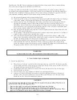
WarninG
: Improper installation, adjustment, alteration,
service or maintenance can cause property damage, injury,
or loss of life. For assistance or additional information, con-
sult a qualified installer, service agency or the gas supplier.
This boiler requires a special venting system. Read these
instructions carefully before installing.
D
E S I G N E D T O
L
E A D
Manufacturer of Hydronic Heating Products
P.O. Box 14818 3633 I. Street
Philadelphia, PA 19134
www.crownboiler.com
Summary of Contents for BIMINI BWC225
Page 2: ......
Page 22: ...20 PAGE INTENTIONALLY LEFT BLANK ...
Page 23: ...21 PAGE INTENTIONALLY LEFT BLANK ...
Page 24: ...22 PAGE INTENTIONALLY LEFT BLANK ...
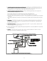
Page 29: ...Figure 8 3 Piping Method 1 Heat Indirect Water Heater 27 ...
Page 37: ...Figure 9 1 Wiring Connections Diagram 35 ...
Page 38: ...Figure 9 2 Ladder Diagram 36 ...
Page 39: ...Figure 9 3 Wiring of Isolation Relay for Control of Two Heating Circulators 37 ...
Page 56: ...54 PAGE INTENTIONALLY LEFT BLANK ...
Page 60: ...58 ...
Page 61: ...59 ...
Page 62: ...60 ...
Page 63: ...61 Gas Train Assembly Honeywell Valve ...
Page 64: ...Gas Train Assembly Dungs Valve 62 ...
Page 66: ...64 ...
Page 68: ...66 ...
Page 69: ...67 ...
Page 70: ...68 ...
Page 72: ......


