


8
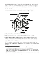
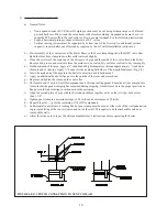
3) Minimum Vent and Air Intake Lengths - Minimum vent length is 2ft. Minimum air inlet length is 2ft.
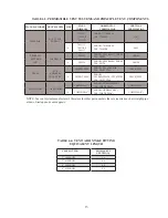
4) Permitted Terminals for Horizontal Venting (Vent Options 1,2) - The vent terminal is either a tee or an elbow
supplied by the vent system manufacturer and equipped with a rodent screen. Vent system manufacturer’s part
numbers for these fittings are shown in Table 6.5. In some cases, the elbows and tees shown in Table 6.5 require
separate rodent screens. When this is the case, vent manufacturer part numbers for these additional parts are shown
in Table 6.5 along with the termination fitting.
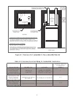
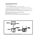
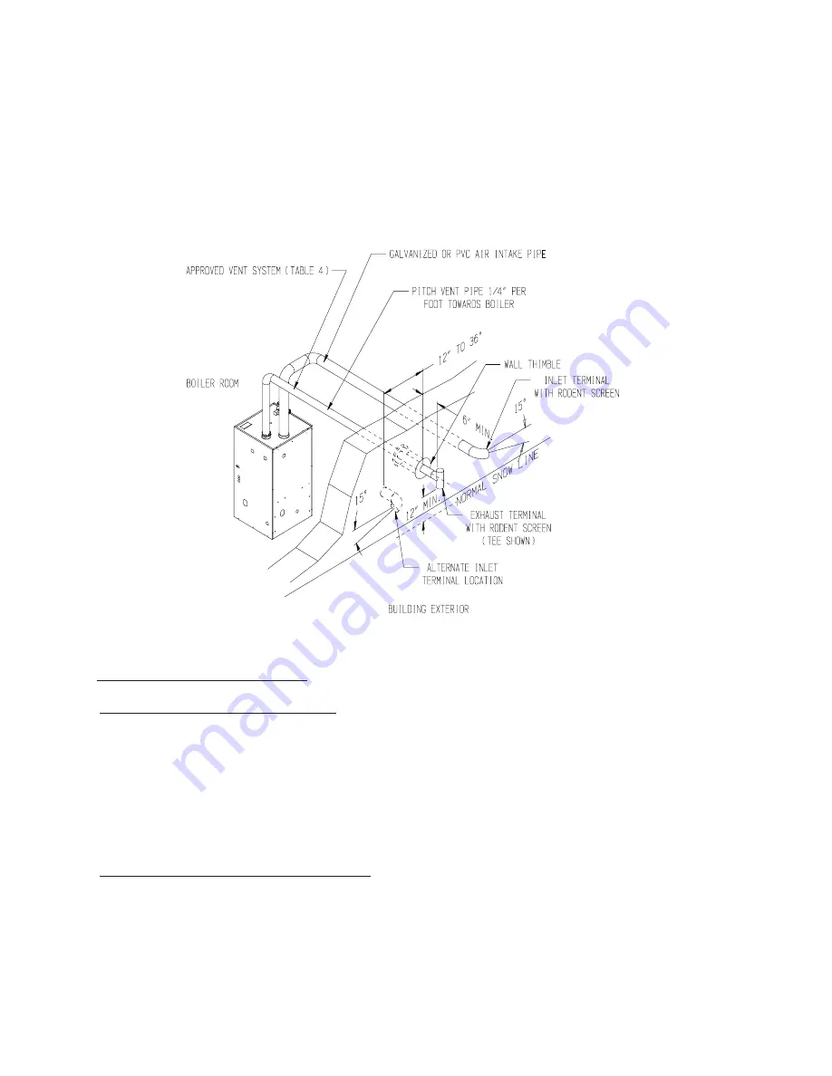
The air intake fitting on a horizontal vent systems is always a 90 degree elbow with a rodent screen. This elbow is
made out of the same material as the rest of the air inlet system (either galvanized or PVC) and is installed as shown
in Figure 6.1.
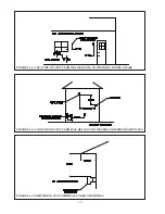
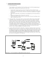
5) Horizontal Vent and Air Intake Terminal Location - Observe the following limitations on the vent terminal location
(also see Figure 6.3):
• Vent terminals must be at least 1 foot from any door, window, or gravity inlet into the building.
• Maintain the correct clearance and orientation between the vent and air intake terminals. The vent and air intake
terminals must be at the same height and their center lines must be between 12 and 36 inches apart. Both terminals
must be located on the same wall.
• The bottom of the vent and air intake terminals must be at least 12” above the normal snow line. In no case should
they be less than 12” above grade level.
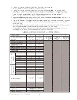
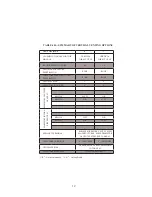
The Vent Option #1 column in Table 6.2a describes a horizontal direct vent system using 3” vent pipe. From this
column, we see that a BWC150 may have a vent length of up to 55ft. The first 90 elbow and the termination elbow
are not considered. From Table 6.6, the equivalent length of the 3” 45 elbow is 4ft and the equivalent length of the
3” 90 degree elbow is 5.5ft. The maximum allowable run of straight pipe on this system is therefore:
55ft – 4 ft – 5.5ft = 40ft
Since the planned installation has only 14 ft of straight pipe, the planned vent length is acceptable
.
FIGURE 6.1: HORIZONTAL DIRECT VENTING (VENT OPTIONS 1,2)
Summary of Contents for BIMINI BWC225
Page 2: ......
Page 22: ...20 PAGE INTENTIONALLY LEFT BLANK ...
Page 23: ...21 PAGE INTENTIONALLY LEFT BLANK ...
Page 24: ...22 PAGE INTENTIONALLY LEFT BLANK ...
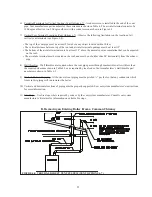
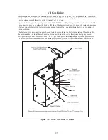
Page 29: ...Figure 8 3 Piping Method 1 Heat Indirect Water Heater 27 ...
Page 37: ...Figure 9 1 Wiring Connections Diagram 35 ...
Page 38: ...Figure 9 2 Ladder Diagram 36 ...
Page 39: ...Figure 9 3 Wiring of Isolation Relay for Control of Two Heating Circulators 37 ...
Page 56: ...54 PAGE INTENTIONALLY LEFT BLANK ...
Page 60: ...58 ...
Page 61: ...59 ...
Page 62: ...60 ...
Page 63: ...61 Gas Train Assembly Honeywell Valve ...
Page 64: ...Gas Train Assembly Dungs Valve 62 ...
Page 66: ...64 ...
Page 68: ...66 ...
Page 69: ...67 ...
Page 70: ...68 ...
Page 72: ......


