


18
5) Assembly of Protech FasNSeal
a) FasNSeal General Notes:
• Do not cut 4” FasNSeal pipe. Consult FasNSeal instructions for method of cutting other 3” pipe.
• Orient FasNSeal vent components so that the arrows on the piping labels are in the direction of flue
gas flow.
• Support horizontal piping sections at intervals of 6 feet or less.
• Vertical venting systems must be supported by at least one FasNSeal support. An additional vertical
support is required after any offset.
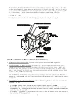
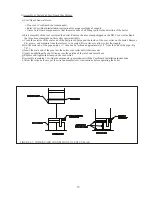
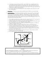
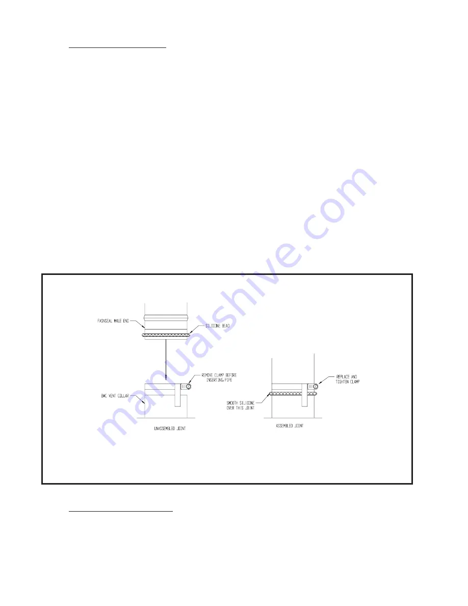
b) Remove the hose clamp shipped on the BWC vent collar. Bend the three hose clamp tabs on this collar
outward slightly. Clean the exterior of the male end of the first piece of pipe and the inside of the vent
collar on the boiler. Remove dirt, grease, and moisture from the surfaces to be sealed. On the male
end of the pipe, apply a ¼” wide bead of high temperature silicone approximately 1/4 inch from the male
end of the pipe. Insert the male end of the pipe into the boiler vent collar until it bottoms out. Apply an
additional bead of silicone over the outside of the joint and the seams on the vent collar and smooth out
(Fig 6.10). Replace and tighten the clamp on the vent collar.
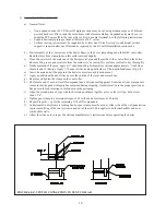
c) All other joints in the FasNSeal venting system rely on a gasket in the female end of the pipe for a proper
seal.
d) Align the longitudinal seam of both pipes. Insert the male end of the second pipe into the female end of the
first pipe until the bead on the male end contacts the flare on the female end.
e) Tighten the locking band with a nut driver.
f) Repeat (d) and (e) for the remaining FasNSeal components.
g) Allow the silicone to cure per the silicone manufacturer’s instructions before operating the boiler.
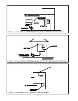
FIGURE 6.10: FASNSEAL CONNECTION TO VENT COLLAR
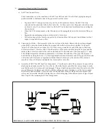
6) Assembly of the air intake system:
a) Assemble the air intake system using either galvanized or PVC pipe.
b) If PVC piping is used, use PVC cement to assemble the PVC intake system components.
c) If galvanized piping is used, use at least two sheet metal screws per joint. Seal the outside of all joints.
Summary of Contents for BIMINI BWC225
Page 2: ......
Page 22: ...20 PAGE INTENTIONALLY LEFT BLANK ...
Page 23: ...21 PAGE INTENTIONALLY LEFT BLANK ...
Page 24: ...22 PAGE INTENTIONALLY LEFT BLANK ...
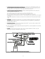
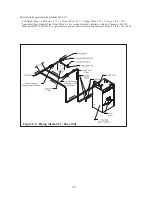
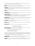
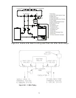
Page 29: ...Figure 8 3 Piping Method 1 Heat Indirect Water Heater 27 ...
Page 37: ...Figure 9 1 Wiring Connections Diagram 35 ...
Page 38: ...Figure 9 2 Ladder Diagram 36 ...
Page 39: ...Figure 9 3 Wiring of Isolation Relay for Control of Two Heating Circulators 37 ...
Page 56: ...54 PAGE INTENTIONALLY LEFT BLANK ...
Page 60: ...58 ...
Page 61: ...59 ...
Page 62: ...60 ...
Page 63: ...61 Gas Train Assembly Honeywell Valve ...
Page 64: ...Gas Train Assembly Dungs Valve 62 ...
Page 66: ...64 ...
Page 68: ...66 ...
Page 69: ...67 ...
Page 70: ...68 ...
Page 72: ......


