


30
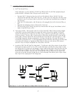
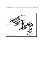
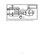
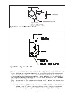
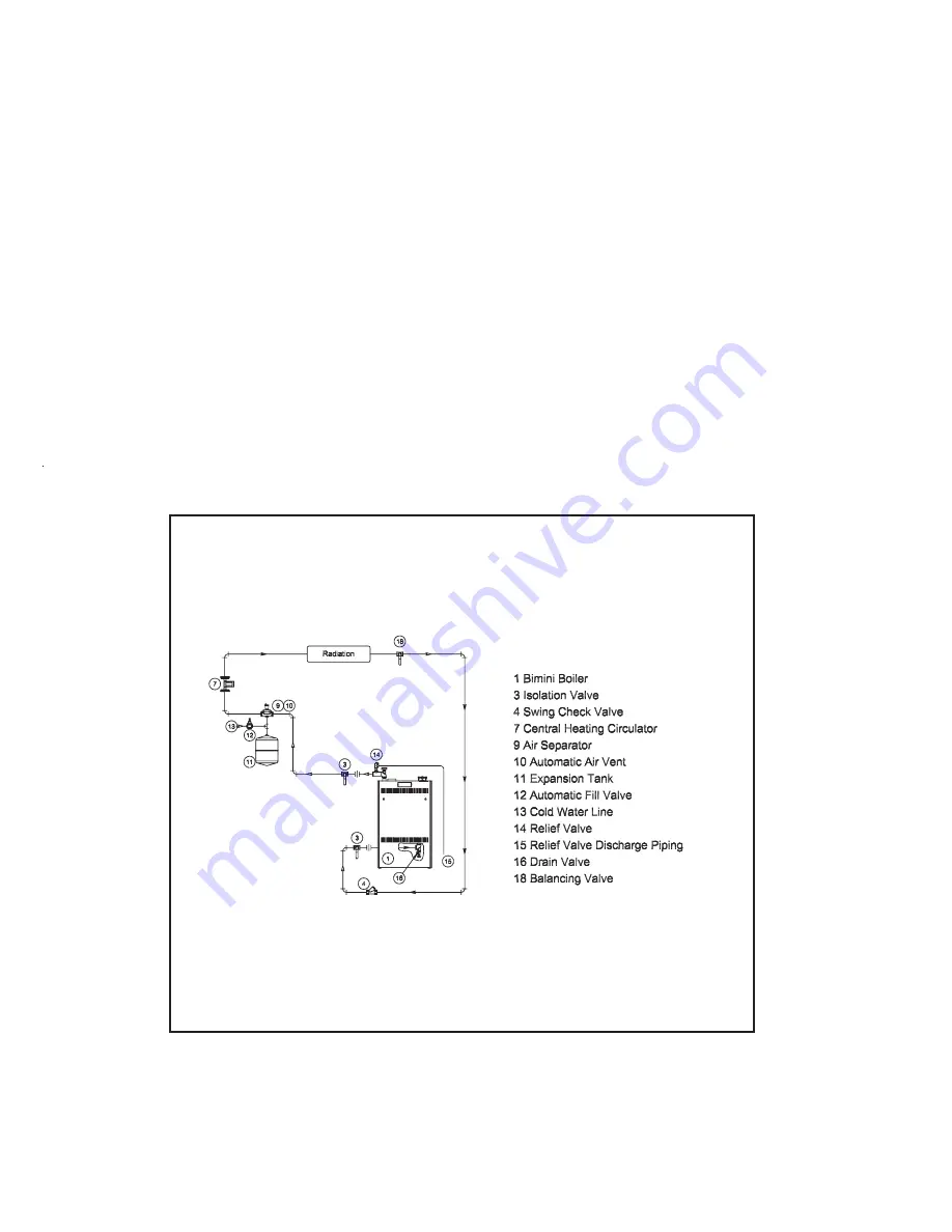
Figure 8.8: Piping Method #2 - Direct Connection of Boiler to Heating System
Method 2: Direct Connection to Heating System (Generally NOT Recommended)
The BWC can be connected directly to the heating system as is done with conventional boilers (Figure 8.8). If
this is done, the flow rate through the boiler will equal the flow rate through the system. The flow rate through the
system must therefore always remain within the limits shown in Table 8.1. For this reason, the pressure drop through
the entire system must be known, added to the boiler pressure drop, and a circulator selected which will provide the
required flow at the total calculated pressure drop.
This method is generally not recommended because it is often very difficult to accurately calculate the pressure
drop through the system. In replacement installations, it may be impossible to get an accurate measurement of the
amount of piping and number of fittings in the system. In addition, if the system is zoned, the system flow may drop
well below the minimum required when only one zone is calling for heat.
The one advantage to this method is its installation simplicity. It may make sense to use this method when the
boiler is to be installed with a new single zone system having a low-pressure drop. Pressure drop curves for the
BWC Series boilers are shown in Figure 8.9. Calculation of the system pressure drop, and selection of the
circulator, must be performed by someone having familiarity with pressure drop calculations, such as an HVAC
engineer.
Summary of Contents for BIMINI BWC225
Page 2: ......
Page 22: ...20 PAGE INTENTIONALLY LEFT BLANK ...
Page 23: ...21 PAGE INTENTIONALLY LEFT BLANK ...
Page 24: ...22 PAGE INTENTIONALLY LEFT BLANK ...
Page 29: ...Figure 8 3 Piping Method 1 Heat Indirect Water Heater 27 ...
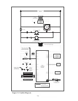
Page 37: ...Figure 9 1 Wiring Connections Diagram 35 ...
Page 38: ...Figure 9 2 Ladder Diagram 36 ...
Page 39: ...Figure 9 3 Wiring of Isolation Relay for Control of Two Heating Circulators 37 ...
Page 56: ...54 PAGE INTENTIONALLY LEFT BLANK ...
Page 60: ...58 ...
Page 61: ...59 ...
Page 62: ...60 ...
Page 63: ...61 Gas Train Assembly Honeywell Valve ...
Page 64: ...Gas Train Assembly Dungs Valve 62 ...
Page 66: ...64 ...
Page 68: ...66 ...
Page 69: ...67 ...
Page 70: ...68 ...
Page 72: ......


