


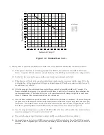


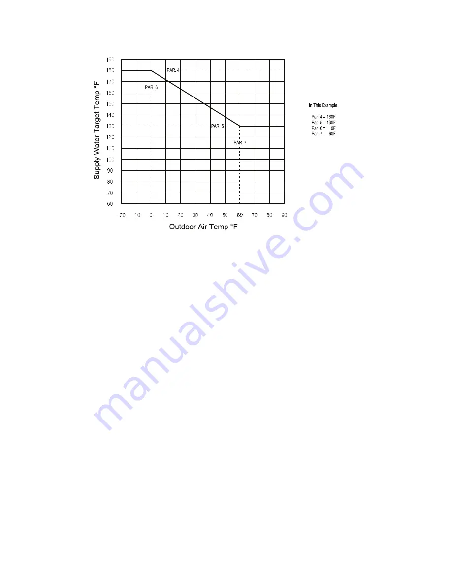
Figure 11.4: Outdoor Reset Curve
48
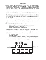
7) The sequence of operation for a BWC series boiler on a call for heat from a thermostat is as described below:
a) When power is first turned on, 120V is provided to the MCBA, the combustion fan and the LWCO trans-
former. A separate 50VA transformer, connected directly to the MCBA, powers all other low voltage circuits.
b) For the first few seconds after power-up the control module goes through a self check.
c) When there is a call for heat, the control module checks to make sure the air pressure switch is open. If it is, the
combustion fan will be energized and will ramp up to ignition speed. When the air pressure switch closes, a 10
second prepurge is activated.
d) After the prepurge, the control module energizes the gas control valve and the spark for 4.5 seconds. If a
flame is established and proved, the control allows the flame to stabilize for 5 seconds at the combustion fan
ignition speed setting. If the flame fails to prove, the control module will attempt to light the burner 4 more
times. If a flame is still not established, the control will lockout.
e) Once the flame stabilization period has ended, the MCBA allows the burner to modulate. The actual firing rate
is dependent upon the measured current and recent differences between the set point temperature and the supply
temperature. If an outdoor sensor is connected to the control module and the boiler is responding to a call for
heat, the set point temperature will be determined by the outdoor reset curve shown in Figure 11.4.
f) Once the set point temperature is reached, the MCBA will turn the burner off and allow the combustion fan to
operate in postpurge for 35 seconds before it turns off.
g) The central heating pump will continue to operate until the room thermostat has been satisfied.
h) A demand for domestic hot water (DHW) is given priority on BWC series boilers. If a call for DHW is received
while the boiler is responding to a call for heat, the heating circulator is deenergized until the call for DHW is
satisfied.
Summary of Contents for BIMINI BWC225
Page 2: ......
Page 22: ...20 PAGE INTENTIONALLY LEFT BLANK ...
Page 23: ...21 PAGE INTENTIONALLY LEFT BLANK ...
Page 24: ...22 PAGE INTENTIONALLY LEFT BLANK ...
Page 29: ...Figure 8 3 Piping Method 1 Heat Indirect Water Heater 27 ...
Page 37: ...Figure 9 1 Wiring Connections Diagram 35 ...
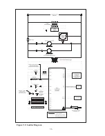
Page 38: ...Figure 9 2 Ladder Diagram 36 ...
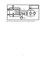
Page 39: ...Figure 9 3 Wiring of Isolation Relay for Control of Two Heating Circulators 37 ...
Page 56: ...54 PAGE INTENTIONALLY LEFT BLANK ...
Page 60: ...58 ...
Page 61: ...59 ...
Page 62: ...60 ...
Page 63: ...61 Gas Train Assembly Honeywell Valve ...
Page 64: ...Gas Train Assembly Dungs Valve 62 ...
Page 66: ...64 ...
Page 68: ...66 ...
Page 69: ...67 ...
Page 70: ...68 ...
Page 72: ......


