background image

WARNING

: Improper installation, 

adjustment, alteration, service or 

maintenance can cause property 

damage, injury, or loss of life. For 

assistance or additional information, 

consult a qualified installer, service 

agency  or  the gas supplier. Read 

these instructions carefully before 

installing.

Models:

• 

CWD060

• 

CWD083  

• 

CWD110

• 

CWD138

• 

CWD165

• 

CWD193

• 

CWD220

• 

CWD245

CWD Series

 Gas-Fired Direct Vent Hot Water Boilers
 INSTALLATION INSTRUCTIONS

 These instructions must be affixed on or adjacent to the boiler

D

E S I G N E D   T O  

L

E A D

Manufacturer of Hydronic Heating Products

P.O. Box 14818  3633 I. Street

Philadelphia, PA  19134

www.crownboiler.com

Equipped with Honeywell 

S9361A Control System

9902339

Summary of Contents for CWD060

Page 1: ...instructions carefully before installing Models CWD060 CWD083 CWD110 CWD138 CWD165 CWD193 CWD220 CWD245 CWD Series Gas Fired Direct Vent Hot Water Boilers INSTALLATION INSTRUCTIONS These instructions...

Page 2: ...2 2...

Page 3: ...lation start up or service Improper installation adjustment alteration service or maintenance may cause serious property damage personal injury or death DO NOT DISCONNECT PIPE FITTINGS on the boiler o...

Page 4: ...ntilation 6 VI Venting 12 Vent System Design 12 Vent System Assembly 25 VII Gas Piping 36 VIII System Piping 37 IX Wiring 42 X Start up and Checkout 46 XI Operation 50 XII Service and Maintenance 58 X...

Page 5: ...NS INPUT MBH HEATING CAPACITY MBH NET AHRI RATING WATER MBH AFUE FIG 2 1 DIM A in VENT DIA in WATER CONTENT Gal CWD060 3 60 51 44 85 1 16 1 8 3 2 0 CWD083 4 82 5 71 62 85 1 19 3 4 3 2 6 CWD110 5 110 9...

Page 6: ...visions to protect the boiler against low return temperatures Failure to provide such provisions if needed could result in severe corrosion damage to the boiler For more information on when low water...

Page 7: ...5 5 FIGURE 4 1a CLEARANCES WHEN BOILER IS DIRECT VENTED OUTDOOR COMBUSTION AIR IS USED FIGURE 4 1b CLEARANCES WHEN COMBUSTION AIR IS OBTAINED FROM BOILER ROOM...

Page 8: ...ARD VERTICAL WITH NO OFFSETS ENCLOSED ON ALL FOUR SIDES 6 PROTECH FASNSEAL W2 VERTICAL OR HORIZONTAL ENCLOSED ON ALL FOUR SIDES 3 HEAT FAB SAF T VENT SC VERTICAL OR HORIZONTAL UNENCLOSED OR ENCLOSED O...

Page 9: ...ds of BTU hr If the result is less than 50 the boiler room is a confined space Example A CWD245 and a water heater are to be installed in a room measuring 6ft 3 in x 7ft with an 8 ft ceiling The water...

Page 10: ...imension is 3 inches Minimum opening free area is 100 square inches per opening If the total volume of both the boiler room and the room to which the openings connect is less than 50 cubic feet per 10...

Page 11: ...9 9 FIGURE 5 1 BOILER INSTALLED IN A CONFINED SPACE VENTILATION OR COMBUSTION VENTILATION AIR FROM INSIDE FIGURE 5 2 ALLAIR FROM OUTSIDE USING VENTILATED CRAWL SPACE AND ATTIC...

Page 12: ...10 10 FIGURE 5 3 ALLAIR FROM OUTSIDE USING VENTILATED ATTIC FIGURE 5 4 ALLAIR FROM OUTSIDE USING OPENINGS INTO BOILER ROOM...

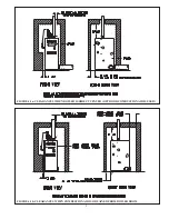
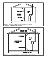
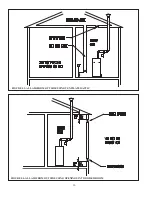
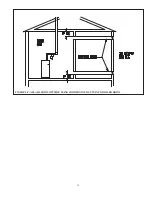
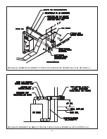
Page 13: ...11 11 FIGURE 5 5 ALLAIR FROM OUTSIDE USING HORIZONTAL DUCTS INTO BOILER ROOM...

Page 14: ...an be done Heat Fab Saf T Vent SC is a double wall vent system which can be used in two ways on CWD installations In vertical coaxial vent systems Vent Options 12 and 13 the space between the inner an...

Page 15: ...55 FT 55 FT CWD165 35 FT 55 FT 35 FT 55 FT CWD193 25 FT 55 FT 25 FT 55 FT CWD220 15 FT 55 FT 15 FT 55 FT CWD245 N R 55FT 10 FT 55 FT MAXIMUM INTAKE PIPE LENGTH CWD060 CWD138 60 FT 60 FT N A N A CWD16...

Page 16: ...14 14 FIGURE 6 2a HORIZONTAL DIRECT VENTING USING SEPARATE TERMINALS VENT OPTIONS 1 2 FIGURE 6 2b HORIZONTAL DIRECT VENTING USING COAXIAL TERMINAL VENT OPTIONS 1 2...

Page 17: ...to be counted when counting additional elbows Example A 3 vent system is planned for a horizontal direct vented CWD165 which has the following components 2 ft vertical pipe 1 90 elbow 5 ft horizontal...

Page 18: ...least 7 feet above a public walkway The bottom of the exhaust elbow tee or coaxial terminal must be at least 3 feet above any forced air inlet located within 10 feet A clearance of at least 4 feet ho...

Page 19: ...e at least 12 above the normal snow accumulation that can be expected on the roof 9 Terminal offsets Horizontal elbow or tee terminals may be offset by as much as 5 ft as shown in Figure 6 10 This som...

Page 20: ...18 18 FIGURE 6 4 VERTICAL NON COAXIAL DIRECT VENT SYSTEM VENT OPTIONS 6 7 FIGURE 6 5 VERTICAL DIRECT EXHAUST SYSTEM VENT OPTIONS 9 10...

Page 21: ...LENGTH CWD060 CWD138 52 FT 50 FT 50 FT CWD165 32 FT 32 FT CONSULT FACTORY CWD193 N R N R CWD220 N R N R CWD245 N R N R EXHAUST TERMINAL BY VENT SYSTEM MANUFAC TURER SAME DIAMETER AS VENT SYSTEM SEE T...

Page 22: ...20 20 FIGURE 6 6 VERTICAL COAXIAL DIRECT VENT USING CROWN 500005 VENT KIT VENT OPTION 11 FIGURE 6 7 VERTICAL COAXIAL DIRECT VENT USING HEAT FAB SAF T VENT SC VENT OPTIONS 12 13...

Page 23: ...04 METAL FAB CORR GUARD 3 CGSWDS 3 CGSWWPK 3 ELBOW CGSW90LTM 3 TEE CGSWTTM 3 CGSWC 3 4 CGSWDS 4 CGSWWPK 4 ELBOW CGSW90LTM 4 TEE CGSWTTM 4 CGSWC 4 NOTES 1 See vent system manufacturer s literature for...

Page 24: ...aces of the building Turn on clothes dryers and any appliance not connected to the common venting system Turn on any exhaust fans such as range hoods and bathroom exhausts so they will operate at maxi...

Page 25: ...23 23 FIGURE 6 11a LOCATION OF DIRECT VENT TERMINAL RELATIVE TO WINDOWS DOORS GRADE FIGURE 6 10 HORIZONTAL TERMINAL OFFSETS...

Page 26: ...E 6 11b LOCATION OF DIRECT EXHAUST TERMINAL RELATIVE TO WINDOWS DOORS GRADE FIGURE 6 11c LOCATION OF VENT TERMINAL RELATIVE TO METERS AND FORCED AIR INLETS FIGURE 6 11d POSITIONING VENT TERMINAL UNDER...

Page 27: ...m manufacturer s manual Where such differences exist this manual takes precedence over the vent system manufacturer s manual CAUTION Vent systems made by Heat Fab Protech and Z Flex rely on gaskets fo...

Page 28: ...n with a package of the silicone lubricant provided and then push the intake terminal firmly onto the straight section until the intake terminal makes contact with the bead on the straight section Sec...

Page 29: ...27 27 FIGURE 6 14a CROWN COAXIAL TERMINAL EXPLODED VIEW FIGURE 6 14b CROWN COAXIAL TERMINALASSEMBLY...

Page 30: ...boiler Remove dirt grease and moisture from the surfaces to be sealed Dry surfaces or allow to dry thoroughly d On the male end of the pipe apply a wide bead of silicone approximately 1 2 from the end...

Page 31: ...h The female end of each Z Vent III component has a silicone sealing gasket Examine all vent components to insure that the gasket integrity has remained during shipping Gaskets must be in the proper...

Page 32: ...ongitudinal weld Insert the male end of the pipe into the boiler vent collar until it bottoms out Apply an additional bead of silicone over the outside of the joint and smooth out Fig 6 17 Apply silic...

Page 33: ...ection into the adaptor until the outer jacket has made contact with the snap ring located inside the female end of the adaptor When fully assembled the outer female end will overlap the male end by 1...

Page 34: ...lamp opening in the FasNSeal pipe Tighten the terminal hose clamp to mechanically lock the pipe onto the terminal g Allow the silicone to cure per the silicone manufacturer s instructions before opera...

Page 35: ...system over the vent pipe Secure and seal it in accordance with the vent manufacturer s instructions Note this collar provides a watertight seal between the vent piping and the concentric air intake h...

Page 36: ...34 34 FIGURE 6 20 INSTALLATION OF VENT SUPPORT PROVIDED IN CROWN 500005 VERT COAXIAL VENT KIT FIGURE 6 21 CONDENSATE TRAP DRAIN DETAIL...

Page 37: ...using termination elbows or tees the rodent screen provided is mounted in the air inlet elbow A second screen is required for the exhaust elbow This second screen can be any one of the following items...

Page 38: ...operation When doing this the boiler and its individual shut off must be disconnected from the rest of the system during any pressure testing of that system at pressures in excess of psi When pressure...

Page 39: ...ly be reused If the expansion tank must be replaced consult the expansion tank manufacturer s literature for proper sizing 4 Fill Valve Required Either a manual or automatic fill valve may be used The...

Page 40: ...wn If the circulator is mounted on the supply the bypass must be on the discharge side of the circulator 3 Low Temperature Systems Some systems such as radiant tubing systems require the system water...

Page 41: ...39 39 FIGURE 8 1 BASIC PIPING FIGURE 8 2 INDIRECT WATER HEATER BOILER SIDE PIPING...

Page 42: ...40 40 FIGURE 8 3 BYPASS PIPING FIGURE 8 4 ISOLATION OF BOILER FROM SYSTEM WITH HEAT EXCHANGER...

Page 43: ...41 41 FIGURE 8 5 CHILLER PIPING...

Page 44: ...AC Neutral White Heating Circulator Hot Red Heating Circulator Neutral White DHW Circulator Hot Blue DHW Circulator Neutral White The use of the Circulator outputs are as follows a Heating Circulator...

Page 45: ...d to the low voltage connections is a transformer in old thermostat wiring Do not attempt to use EnviraCom connections for any purpose not explicitly permitted by Crown Boiler Company Attempting to do...

Page 46: ...44 44 FIGURE 9 2 INTERNAL CONNECTIONS DIAGRAM...

Page 47: ...45 45 FIGURE 9 3 LADDER DIAGRAM...

Page 48: ...center one should be a steady medium blue flame covering around 3 8 to of spark electrode flame rod Figure 10 1 9 Inspect the main burner flames visible through the observation port in burner access...

Page 49: ...tion above on this label 2 Set the thermostat to lowest setting 3 Turn off all electric power to the appliance 4 This appliance is equipped with an ignition device which automatically lights the pilot...

Page 50: ...ssure If a manifold pressure adjustment is made recheck the line pressure to be certain that it is still within acceptable limits Replace the cover screw on the regulator f Reconnect the silicone regu...

Page 51: ...49 49 FIGURE 10 3 GAS VALVE FIGURE 10 4 MEASURING MANIFOLD PRESSURE...

Page 52: ...rent status of the boiler A list and description of these status numbers is shown in Table 11 3 and is also shown on the face of the control itself 2 Operating Mode Provides additional information abo...

Page 53: ...MODE Visible when Lockout is Present Code for Error Present Table 13 0 total burner Cycles Total Run Time hrs Press I Return to Status Mode Press or Boiler in Lockout Temperature Units Reset Circulat...

Page 54: ...re switch remained closed Boiler will remain in this state until the air pressure switch opens 12 Pressure Switch failed to close Control waited in Status 3 for 60 seconds and air pressure switch fail...

Page 55: ...HW Note that if the dh zone on the S9361A is used as a second heating zone see Table 11 6 this parameter will be shown as OFF and tt will be shown as ON when this zone calls for heat FLA Flame Current...

Page 56: ...end while the burners are off on high limit the burner will not restart during the next call for heat until the thermal purge requirements described below are met Or Circulator Overrun Determines how...

Page 57: ...w 140 Pt DHW Priority If this feature is turned on and simultaneous calls for heat and DHW are present the heating circulator will be forced off for as long as it takes the boiler to satisfy the call...

Page 58: ...that the air pressure switch APS is open before starting the fan 4 The control energizes the fan and waits for the air pressure switch to close 5 Once the air pressure switch closes the control waits...

Page 59: ...identical to that described above except for omission of the thermal purge function described in 2 E Safety Control Operation Air Pressure Switch APS The APS proves that the fan is running before all...

Page 60: ...trap is 1 8 Inspect the porcelain for cracks or other deterioration Replace pilot assembly if deterioration is found Inspect the ignition cable insulation for cracks or other deterioration If deterior...

Page 61: ...ear and left side jacket panels 5 Unplug the fan and remove the fan cover plate WARNING SOOT DEPOSITS IN THE FLUE PASSAGES ARE A SIGN THAT THE BOILER MAY BE OPERATING AT HIGH CARBON MONOXIDE CO LEVELS...

Page 62: ...E WITH THE INTAKE COVER REMOVED 1 Operating the Boiler with Intake Cover Removed For inspection and troubleshooting purposes this boiler may be started and run with the intake cover removed When this...

Page 63: ...N APPROX MAKE SETTING inches w c BREAK SETTING inches w c CWD060 CWD110 620039 1 21 1 16 CWD138 CWD220 620040 1 40 1 35 CWD245 620041 1 45 1 40 Settings shown are based on plus tolerance actual settin...

Page 64: ...62 62 FIGURE 12 2b MEASURING PRESSURE ACROSS PRESSURE SWITCH...

Page 65: ...ry to rule out all other possible causes 5 When checking voltage across at wiring connectors be careful not to insert the meter probes into the metal sockets Do ing so may damage the socket resulting...

Page 66: ...rol 35 Duplicate Zone Error code reserved for future use 57 Grounded pilot electrode Condensate or foreign material is shorting pilot electrode to ground Ignition cable insulation is damaged and touch...

Page 67: ...strap damaged replace pilot If you cannot hear spark at all replace control StA 6 Spark but no pilot flame Low inlet gas pressure Plugged kinked or leaking pilot tubing Plugged pilot orifice Gas line...

Page 68: ...66 66 Notes...

Page 69: ...a Crown representative or the factory at Crown Boiler Co Customer Service P O Box 14818 Philadelphia Pa 19134 www crownboiler com Main burner orifice shown are for sea level configured boilers For boi...

Page 70: ...537 620538 620539 620540 22 1 1 4 CUP HEAD PIN 900203 4 4 6 6 6 6 6 6 23 1 1 4 SELF LOCKING WASHER 900200 4 4 6 6 6 6 6 6 24 1 CERAFELT SEALING STRIP 900145 0 75 FT 1 05 FT 1 35 FT 1 65 FT 1 95 FT 2 2...

Page 71: ...69 69...

Page 72: ...59 3 4 90 DEGREE FLANGE 35 1055 1 1 1 1 1 1 1 1 60 HONEYWELL VR8204C2328 GAS VALVE NAT GAS 3507400 1 1 1 1 1 0 0 0 60 HONEYWELL VR8304P2342 GAS VALVE NAT GAS 3507410 0 0 0 0 0 1 1 1 60 HONEYWELL VR820...

Page 73: ...71 71...

Page 74: ...ET METAL SCREW 90 212 31 31 32 31 34 36 36 36 84 LH JACKET PANEL 620301 1 1 1 1 1 1 1 1 85 RH JACKET PANEL 620300 1 1 1 1 1 1 1 1 86 REAR JACKET PANEL 1 620303 620304 620305 620306 620307 620308 62030...

Page 75: ...73 73...

Page 76: ...0 TRANSFORMER AT72D1006 35 2100 1 1 1 1 1 1 1 1 111 1 1 2 X 1 1 4 BLACK 90 DEGREE ELBOW 950200 1 1 1 1 1 1 1 1 112 ISOLATION FLANGE SET 95 061 1 1 1 1 1 1 1 1 113 TACO 007 CIRCULATOR 95 012 1 1 1 1 1...

Page 77: ...75 75...

Page 78: ...a product approved air intake must be used Installation shall be in strict compliance with the manufacturer s instructions A copy of the installation instructions shall remain with the appliance or e...

Page 79: ...Notes...

Page 80: ...PN 980060 CWDMANV9 06 15 Manufacturer of Hydronic Heating Products P O Box 14818 3633 I Street Philadelphia PA 19134 www crownboiler com...

Reviews: