


8
8
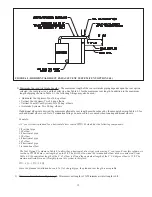
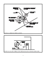
floor (Fig 3). The minimum opening dimension is 3 inches.
• If the CWD boiler is the only gas-burning appliance in the boiler room, these openings must each have a free area of 100
square inches.
• If other gas-burning appliances are in the boiler room, size the openings in accordance with the appliance manufacturer’s
instructions or the National Fuel Gas Code. Minimum opening free area is 100 square inches regardless of opening
requirements for other appliances.
• If the total volume of both the boiler room and the room to which the openings connect is less than 50 cubic feet per 1000
BTU/hr of total appliance input, install a pair of identical openings into a third room. Connect additional rooms with
openings until the total volume of all rooms is at least 50 cubic feet per 1000 BTU/hr of input.
• The “free area” of an opening takes into account the blocking effect of mesh, grills, and louvers. Where screens are used,
they must be no finer than ¼” (4 x 4) mesh.
Step 5: If Indoor Combustion Air is Used, Provide Air as Follows:
1) Buildings of other than unusually tight construction:
Unconfined Space– Natural infiltration into the boiler room will normally provide adequate air for combustion and
ventilation without additional louvers or openings into boiler room.
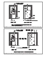
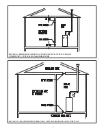
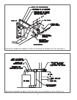
Confined Space – Provide two openings into the boiler room, one near the floor and one near the ceiling. The top edge of
the upper opening must be within 12” of the ceiling and the bottom edge of the lower opening must be within 12” of the
floor (Fig 5.1).
• Each opening must have a free area of 1 square inch per 1000 BTU/hr input of all gas burning appliances in the boiler
room. The minimum opening dimension is 3 inches. Minimum opening free area is 100 square inches per opening.
• If the total volume of both the boiler room and the room to which the openings connect is less than 50 cubic feet per 1000
BTU/hr of total appliance input, install a pair of identical openings into a third room. Connect additional rooms with
openings until the total volume of all rooms is at least 50 cubic feet per 1000 BTU/hr of input.
• The “free area” of an opening takes into account the blocking effect of mesh, grills, and louvers. Where screens are used,
they must be no finer than ¼” (4 x 4) mesh.
2) Buildings of unusually tight construction:
If at all possible, direct vent the boiler. Where the boiler must be installed in unusually tight construction and cannot be
direct vented, openings must be installed between the boiler room and the outdoors or a ventilated space, such as an attic
or crawl space, which communicates directly with the outdoors. Two openings are required. The top edge of the upper
opening must be within 12 inches of the ceiling. The bottom edge of the lower opening must be within 12 inches of the
floor. Size openings and ducts as follows:
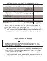
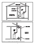
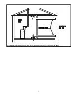
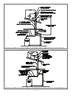
• Vertical ducts or openings directly outdoors (Fig 5.2, Fig 5.3, Fig 5.4) – Each opening must have a free cross sectional
area of 1 square inch per 4000 BTU/hr of the total input of all gas-fired appliances in the boiler room but not less than 100
square inches. Minimum opening size is 3 inches.
• Openings to outdoors via horizontal ducts (Fig 5.5) - Each opening must have a free cross sectional area of 1 square
inch per 2000 BTU/hr of the total input of all gas fired appliances in the boiler room but not less than 100 square inches.
Minimum opening size is 3 inches.
• The “free area” of an opening takes into account the blocking effect of mesh, grills, and louvers. Where screens are used,
they must be no finer than ¼” (4 x 4) mesh.
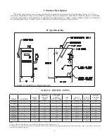
Summary of Contents for CWD060
Page 2: ...2 2...
Page 13: ...11 11 FIGURE 5 5 ALLAIR FROM OUTSIDE USING HORIZONTAL DUCTS INTO BOILER ROOM...
Page 41: ...39 39 FIGURE 8 1 BASIC PIPING FIGURE 8 2 INDIRECT WATER HEATER BOILER SIDE PIPING...
Page 42: ...40 40 FIGURE 8 3 BYPASS PIPING FIGURE 8 4 ISOLATION OF BOILER FROM SYSTEM WITH HEAT EXCHANGER...
Page 43: ...41 41 FIGURE 8 5 CHILLER PIPING...
Page 46: ...44 44 FIGURE 9 2 INTERNAL CONNECTIONS DIAGRAM...
Page 47: ...45 45 FIGURE 9 3 LADDER DIAGRAM...
Page 51: ...49 49 FIGURE 10 3 GAS VALVE FIGURE 10 4 MEASURING MANIFOLD PRESSURE...
Page 64: ...62 62 FIGURE 12 2b MEASURING PRESSURE ACROSS PRESSURE SWITCH...
Page 68: ...66 66 Notes...
Page 71: ...69 69...
Page 73: ...71 71...
Page 75: ...73 73...
Page 77: ...75 75...
Page 79: ...Notes...


