


17
17
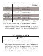
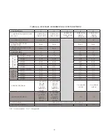
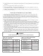
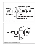
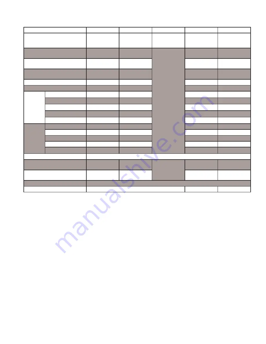
TABLE 6.1b: SUMMARY OF VERTICAL VENTING OPTIONS
VENT OPTION #
6
7
8
9
10
CLASSIFICATION USED IN THIS
MANUAL
VERTICAL
DIRECT VENT
VERTICAL
DIRECT VENT
(RESERVED
FOR FUTURE
USE)
VERTICAL
DIRECT
EXHAUST
VERTICAL
DIRECT
EXHAUST
ILLUSTRATED IN FIGURE
6.4
6.4
6.5
6.5
VENT PIPE STRUCTURE
PENETRATION
ROOF
ROOF
ROOF
ROOF
AIR INTAKE PIPE STRUCTURE
PENETRATION
ROOF OR WALL
ROOF OR WALL
N.A.
N.A.
VENT PIPE SIZE
3”
4”
3”
4”
AIR INTAKE PIPE SIZE
4”
4”
N.A.
N.A.
MAXIMUM
VENT
PIPE LENGTH
CWD060 - CWD138
47 FT
47 FT
47 FT
47 FT
CWD165
27 FT
47 FT
27 FT
47 FT
CWD193
17 FT
47 FT
17 FT
47 FT
CWD220
N.R.
47 FT
N.R.
47 FT
CWD245
N.R.
47 FT
N.R.
47 FT
MAXIMUM INT
AKE PIPE LENGTH
CWD060 - CWD138
52 FT
50 FT
N.A.
N.A.
CWD165
32 FT
50 FT
N.A.
N.A.
CWD193
22 FT
50 FT
N.A.
N.A.
CWD220
N.R.
50 FT
N.A.
N.A.
CWD245
N.R.
50 FT
N.A.
N.A.
EXHAUST TERMINAL
BY VENT SYSTEM MANUFACTURER. SAME DIAMETER AS VENT SYSTEM. SEE TABLE 4.
AIR INTAKE TERMINAL
(ROOF PENETRATION)
4” 180 ELBOW
4” 180 ELBOW
N.A.
N.A.
AIR INTAKE TERMINAL
(WALL PENETRATION)
4” 90 ELBOW
4” 90 ELBOW
N.A.
N.A.
VENT MATERIAL
APPROVED VENT SYSTEM SHOWN IN TABLE 6.8
AIR INTAKE MATERIAL
GALVANIZED OR PVC
N.A.
N.A.
“N.R” - Not recommended “N.A.” - Not applicable
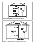
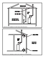
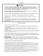
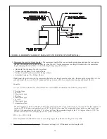
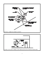
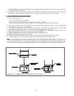
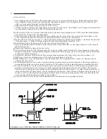
8) Vertical Vent Terminal Locations (Vent Options 6 - 13) - Observe the following limitations on the location of all vertical
vent terminals (see Figs. 6.4, 6.5, 6.6, 6.7):
• The lowest discharge opening on the cap must be at least 2 feet above any object located within 10 feet.
• If outside air is used for combustion (Options 6-7, 11-13), the vertical distance between vent and air inlet terminal
openings must be at least 12”.
• The bottom of the air inlet terminal must be at least 12” above the normal snow accumulation that can be expected on the
roof.
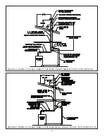
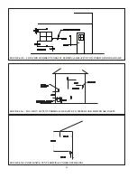
9) Terminal offsets - Horizontal elbow or tee terminals may be offset by as much as 5 ft as shown in Figure 6.10. This
sometimes helps maintain the 12” minimum clearance required above the snow line. The extra two elbows and the section
of vertical pipe on the outside of the building must be counted when checking that the maximum vent / intake pipe length is
not exceeded. On horizontal direct vent systems, both terminals must be offset by the same amount so that their relationship
to one another is the same as shown in Figure 6.2a. When this offset is used, the horizontal section of vent pipe must be
pitched away from the outside so that condensate cannot collect in the lower offset elbow.
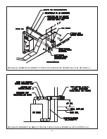
10) Wall thimbles – Wall thimbles are required where the vent pipe passes through combustible walls with less than the
required clearance shown in Table 4.2 or as required by local codes. Vent manufacturer’s wall thimble part numbers are
shown in Table 6.8.
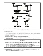
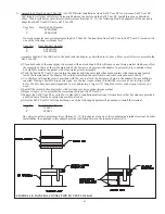
11) Condensate Traps and Pitch of Horizontal piping – All horizontal vent piping must be pitched ¼” per foot so that any
condensate which forms in this piping will run towards either the outdoors or into a condensate trap. Vent manufacturer’s
part numbers for suitable condensate traps are shown in Table 6.8.
All vertical vent systems must include at least one condensate trap as shown in Figures 6.4-6.7. This will collect any
condensate that forms in the vent system as well as any rain water that gets around the vent cap.
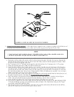
The maximum allowable vertical run directly off of the boiler without a condensate trap is 7.5 ft (Figure 6.12). Install a
condensate trap in longer vertical runs so that condensate which might form in this first vertical section will not run into the
boiler fan.
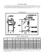
Summary of Contents for CWD060
Page 2: ...2 2...
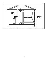
Page 13: ...11 11 FIGURE 5 5 ALLAIR FROM OUTSIDE USING HORIZONTAL DUCTS INTO BOILER ROOM...
Page 41: ...39 39 FIGURE 8 1 BASIC PIPING FIGURE 8 2 INDIRECT WATER HEATER BOILER SIDE PIPING...
Page 42: ...40 40 FIGURE 8 3 BYPASS PIPING FIGURE 8 4 ISOLATION OF BOILER FROM SYSTEM WITH HEAT EXCHANGER...
Page 43: ...41 41 FIGURE 8 5 CHILLER PIPING...
Page 46: ...44 44 FIGURE 9 2 INTERNAL CONNECTIONS DIAGRAM...
Page 47: ...45 45 FIGURE 9 3 LADDER DIAGRAM...
Page 51: ...49 49 FIGURE 10 3 GAS VALVE FIGURE 10 4 MEASURING MANIFOLD PRESSURE...
Page 64: ...62 62 FIGURE 12 2b MEASURING PRESSURE ACROSS PRESSURE SWITCH...
Page 68: ...66 66 Notes...
Page 71: ...69 69...
Page 73: ...71 71...
Page 75: ...73 73...
Page 77: ...75 75...
Page 79: ...Notes...


