


26
26
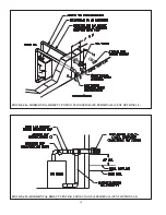
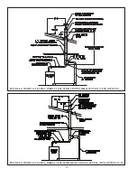
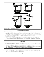
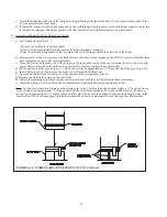
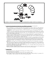
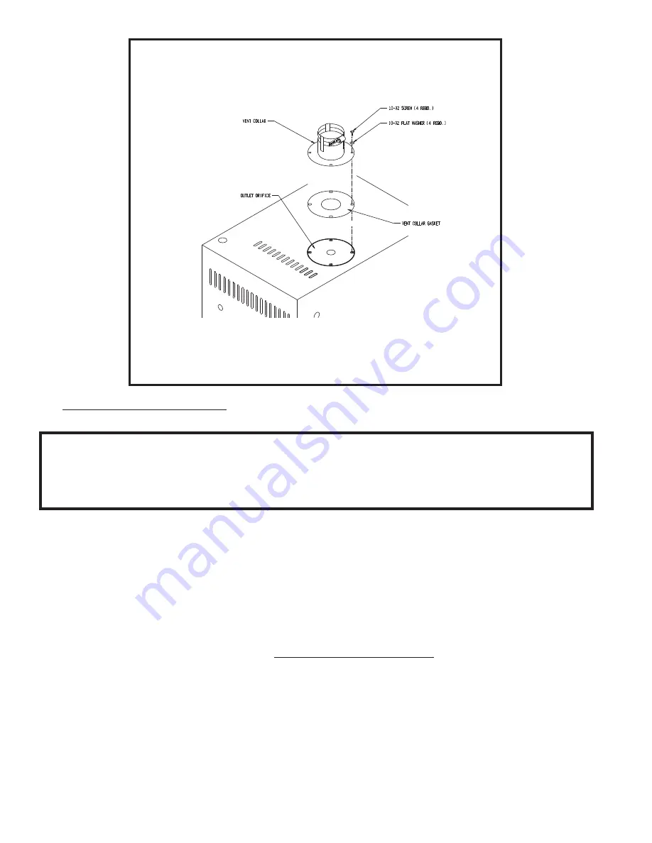
FIGURE 6.13: INSTALLATION OF FAN OUTLET ORIFICE
3)
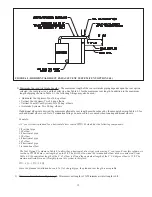
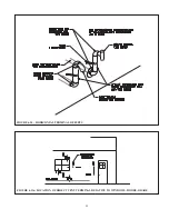
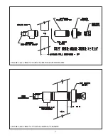
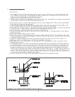
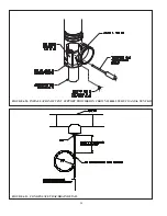
Optional Coaxial Terminal Installation
–
If the optional coaxial terminal is used, it should be installed in the wall before vent
assembly is started. Install the terminal in accordance with the following procedure (Figures 6.14a & 6.14b):
NOTE
• Coaxial portion of inside terminal section may be installed in direct contact with combustible construction.
• Maximum wall thickness through which this terminal can be installed is 10”
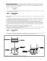
a) Position the wall face plate on the outside wall in the desired terminal location. Verify that this location will permit the
terminal, and connected venting, to clear any obstructions on the inside of the wall with the appropriate clearances. Mark
the location of the round opening on the wall.
b) For 3” terminals, cut a 5 ¼” Diameter hole through the wall at this location. For 4” terminals, cut a 7 1/4” opening.
c) Attach the mounting plate to the outside wall with suitable fasteners.
d) Attach the intake terminal to the straight coaxial section. To do this, clean the male and female ends of the inner pipes
with an alcohol pad. Lubricate the gasket in the female end of the straight section with a package of the silicone lubricant
provided and then push the intake terminal firmly onto the straight section until the intake terminal makes contact with
the bead on the straight section. Secure the two fittings together with the self-drilling screws provided. Use a low torque
setting to install these screws so as not to strip out the holes.
e) Pass the assembled intake terminal and straight section through the wall from the outside. Bend the four Tabs in the wall
face plate towards the outside when doing this. Do not attach the pipe to the plate yet.
f) Adjust the position of the terminal in the wall so that the edge of the intake skirt is 2-3” from the wall plate (Figure
6.14b). Also verify that the terminal is pitched in the same direction as the rest of the vent system.
g) Attach the intake/straight section to the wall face plate using the self drilling screws provided.
h) Loosen the hose clamp on the end of the exhaust terminal. Mount the exhaust terminal onto the intake terminal with the
“V” horizontal (flue gas openings on top and bottom) as shown in Figure 6.14b. Slip the hose clamp over the “fingers”
on the intake terminal and tighten the clamp.
i) Seal all exposed exterior joints, including the joint between the wall face plate and the wall and between the wall face
plate and the straight section with an exterior grade silicone sealant.
Summary of Contents for CWD060
Page 2: ...2 2...
Page 13: ...11 11 FIGURE 5 5 ALLAIR FROM OUTSIDE USING HORIZONTAL DUCTS INTO BOILER ROOM...
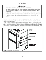
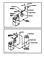
Page 41: ...39 39 FIGURE 8 1 BASIC PIPING FIGURE 8 2 INDIRECT WATER HEATER BOILER SIDE PIPING...
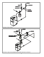
Page 42: ...40 40 FIGURE 8 3 BYPASS PIPING FIGURE 8 4 ISOLATION OF BOILER FROM SYSTEM WITH HEAT EXCHANGER...
Page 43: ...41 41 FIGURE 8 5 CHILLER PIPING...
Page 46: ...44 44 FIGURE 9 2 INTERNAL CONNECTIONS DIAGRAM...
Page 47: ...45 45 FIGURE 9 3 LADDER DIAGRAM...
Page 51: ...49 49 FIGURE 10 3 GAS VALVE FIGURE 10 4 MEASURING MANIFOLD PRESSURE...
Page 64: ...62 62 FIGURE 12 2b MEASURING PRESSURE ACROSS PRESSURE SWITCH...
Page 68: ...66 66 Notes...
Page 71: ...69 69...
Page 73: ...71 71...
Page 75: ...73 73...
Page 77: ...75 75...
Page 79: ...Notes...


