


60
60
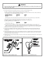
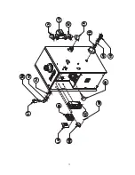
6) Disconnect the pressure switch hoses.
7) Loosen the two ¼-20 nuts and washers in the flue collector lugs. Slide the flue collector lugs off of each flue collector flange.
8) Score the silicone seal around the flue collector with a utility knife or similar tool.
9) Pry the flue collector off of the heat exchanger, being careful not to damage the flue collector or fan.
10 Remove the stainless steel flue baffle from each flue passage.
11) Clean the flue passageways using a stiff bristle brush. Be certain that all foreign material is removed from the gaps between
the pins.
12) Clean the bottom surfaces of the heat exchanger.
13) Put a light in the combustion chamber and look through the flue passages from the top to verify that they have been
thoroughly cleaned.
14) Replace the flue baffles.
15) Apply a heavy (1/4”) bead of silicone with a temperature rating of at least 400F around the perimeter of the heat exchanger.
16) Set the flue collector onto the block and press down so that the flue collector is set into the silicone applied in the previous
step.
17) Slide the flue collector lugs back into position and retighten the ¼-20 bolts.
DO NOT OVER TIGHTEN
.
18) Apply a bead of silicone around the outside of the joint between the heat exchanger and the flue collector.
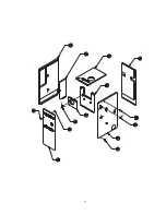
19) Reattach all the jacket components.
20) Reconnect the pressure switch tubes (see Figure 12.2 for correct tubing orientation).
21) Reconnect the fan.
22) Reconnect the vent system.
23) Reinstall the burner tray.
Service Notes
WARNING
DO NOT LEAVE THE BOILER IN SERVICE WITH THE INTAKE COVER REMOVED.
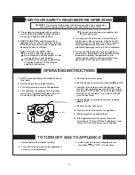
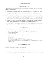
1) Operating the Boiler with Intake Cover Removed – For inspection and troubleshooting purposes, this boiler may be started
and run with the intake cover removed. When this is done, a resonance (“hum”) may be observed. This is normal and
should disappear as soon as the intake cover is replaced.
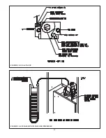
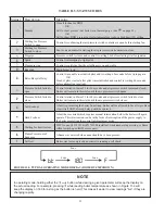
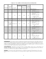
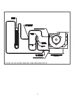
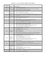
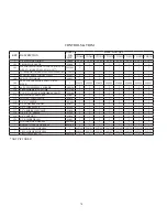
2) Pressure Switch
– This boiler is equipped with a differential pressure switch which makes when there is adequate flue gas
flow through the boiler. This switch measures the pressure drop across an orifice plate inside the flue collector - the higher
the flue gas flow through this plate, the higher the pressure drop. The N.O. contacts on the pressure switch make, allowing
the boiler to fire, when the pressure drop across the flue collector orifice plate switch exceeds the “make setting” shown in
Table 12.1. Once the switch is made, the boiler will fire as long as the pressure at the switch is above the “break setting”
shown in Table 12.1. The pressure at both pressure switch tappings is actually below atmospheric (“negative”) with the
pressure at the upper flue collector tap being the more negative of the two pressures. Figure 12.2a shows the pressure switch
connections.
Figure 12.2b shows the correct method of reading the pressure across the pressure switch tappings. It is normal for the
pressure reading across the switch to drop as the boiler heats up.
3) Burner and Pilot Removal - If necessary, the pilot can be removed without removing the burner tray. To do so, remove the
screws holding the main burners on each side of the pilot bracket. The main burners will then be loose enough to allow the
pilot hood to slip between them.
Main burners cannot be removed without removing the burner tray from the boiler.
Summary of Contents for CWD060
Page 2: ...2 2...
Page 13: ...11 11 FIGURE 5 5 ALLAIR FROM OUTSIDE USING HORIZONTAL DUCTS INTO BOILER ROOM...
Page 41: ...39 39 FIGURE 8 1 BASIC PIPING FIGURE 8 2 INDIRECT WATER HEATER BOILER SIDE PIPING...
Page 42: ...40 40 FIGURE 8 3 BYPASS PIPING FIGURE 8 4 ISOLATION OF BOILER FROM SYSTEM WITH HEAT EXCHANGER...
Page 43: ...41 41 FIGURE 8 5 CHILLER PIPING...
Page 46: ...44 44 FIGURE 9 2 INTERNAL CONNECTIONS DIAGRAM...
Page 47: ...45 45 FIGURE 9 3 LADDER DIAGRAM...
Page 51: ...49 49 FIGURE 10 3 GAS VALVE FIGURE 10 4 MEASURING MANIFOLD PRESSURE...
Page 64: ...62 62 FIGURE 12 2b MEASURING PRESSURE ACROSS PRESSURE SWITCH...
Page 68: ...66 66 Notes...
Page 71: ...69 69...
Page 73: ...71 71...
Page 75: ...73 73...
Page 77: ...75 75...
Page 79: ...Notes...


