background image

24

23

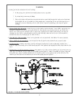
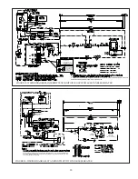
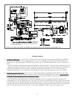
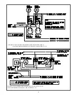
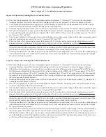
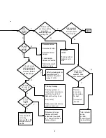
CWI Control System – Sequence of Operation

(Refer to Figures 18 - 21 for ladder and connection diagrams)

Sequence of Operation, Standing Pilot, Less Tankless Heater

1)   When the boiler is energized, 24 volts is immediately applied to terminals “1” (blue) and “4” (yellow) on the vent damper.

Assuming that there is no call for heat, and that the damper switch is in the “automatic” position, the damper will close.

2) A call for heat from the thermostat energizes relay coil 1R (the relay on the L8148E), causing contacts 1R1 and 1R2 to make.

Contact 1R1 starts the circulator. Contact 1R2 sends power to the high limit.

3) Assuming that the high limit is made, current will flow to pin terminal #2 (orange) at the vent damper and the damper will open.
4) Once the vent damper is fully open, an end switch inside the damper will make, energizing pin #3 (red) at the damper. This pin

is connected through the damper harness to terminal “B1” on the L8148E. At this point in the operating sequence, 24 volts is
present across “B1” and “B2”.

5) Under normal conditions, the flame roll-out switch and blocked vent switch are made. Voltage will therefore immediately appear

across the combination gas control (“gas valve”) terminals “TH” and “TR”.

6) When the boiler is first placed into operation, the pilot must be lit. The pilot heats a thermocouple which generates a small

amount of electricity sufficient to hold open the safety shut-off valve in the combination gas control. The circuit connecting
the thermocouple and the safety shut-off valve is self contained and completely independent of all other wiring on the boiler.
This safety shut-off valve is upstream of the 24 volt valves in the gas control which open in response to a call for heat. If the
pilot is not lit, the safety shut-off valve will remain closed and gas will not reach the 24 volt valves.

7) Assuming that the pilot is established and proven by the thermocouple, the application of 24 volts across the combination gas

valve terminals energizes the redundant 24 volt solenoid valves in the combination gas control, resulting in gas flow through
the control and burner operation.


Sequence of Operation, Standing Pilot, With Tankless Heater

1)   When the boiler is energized, 24 volts is immediately applied to terminals “1” (blue) and “4” (yellow) on the vent damper.

Assuming that there is no call for heat, and that the damper switch is in the “automatic” position, the damper will close.

2) If the boiler water temperature is less than the  low limit setting minus the differential setting, terminals “R” and “B” in the

L8124E are made through the low limit switch. The low limit switching action is SPDT with “R” being common. “R” and “W”
are therefore open whenever “R” and “B” are made. This means that while “R” and “B” are made relay coil R1 is deenergized,
regardless of whether or not there is a call for heat. The circulator will therefore not operate if the boiler water temperature is
too low to generate domestic hot water.

3) Assuming that the high limit is made, current will flow to terminal “B1” on the L8124E and then to terminal “2” (orange) at the

vent damper and the damper will open.

4) Once the vent damper is fully open, an end switch inside the damper will make, energizing pin #3 (red) at the damper. The red

wire from this pin runs to the flame rollout switch.

5) Under normal conditions, the flame roll-out switch and blocked vent switch are made. Voltage will therefore immediately appear

across the combination gas control (“gas valve”) terminals “TH” and “TR”.

6) When the boiler is first placed into operation, the pilot must be lit. The pilot heats a thermocouple which generates a small

amount of electricity sufficient to hold open the safety shut-off valve in the combination gas control. The circuit connecting
the thermocouple and the safety shut-off valve is self contained and completely independent of all other wiring on the boiler.
This safety shut-off valve is upstream of the 24 volt valves in the gas control which open in response to a call for heat. If the
pilot is not lit, the safety shut-off valve will remain closed and gas will not reach the 24 volt valves.

7) Assuming that the pilot is established and proven by the thermocouple, the application of 24 volts across the combination gas

valve terminals energizes the redundant 24 volt solenoid valves in the combination gas control, resulting in gas flow through
the control and burner operation.

8) The boiler will fire until the boiler water temperature is approximately equal to the low limit setting. Once the water temperature

reaches this point, “R” and “B” open and “R” and “W” make. At this point, a call for heat will energize 1R, making contacts
1R1 and 1R2. Contacts 1R1 energize the circulator. Contacts 1R2 switch current from the “hot” side of the transformer second-
ary to the high limit switch. If the high limit is made, current flows to terminal “B1” and the ignition sequence is then the same
as it is for a call for burner operation from the low limit (see (3) above).

Summary of Contents for CWI Series

Page 1: ...INSTRUCTIONS These instructions must be affixed on or adjacent to the boiler WARNING Improper installation adjustment alteration service or maintenance can cause property damage injury or loss of lif...

Page 2: ...oduct Description The CWI series boilers are low pressure cast iron gas fired hot water boilers designed for use in closed hot water heating systems These boilers are Category I draft diverter equippe...

Page 3: ...41 202 81 1 83 2 3 75 4 75 29 30 40 7 16 7 18 8 CWI276 9 276 232 81 4 83 2 4 00 5 25 32 1 4 30 40 7 16 8 21 0 CWI310 10 310 259 4 00 5 25 35 1 2 30 45 7 16 8 23 2 CWI345 11 345 288 4 00 5 25 38 3 4 30...

Page 4: ...tural or LP The CWI345 and CWI379 may only be used with natural gas 5 Boilers installed at altitudes above 2000 ft may require different burners and main burner orifice than those at sea level Make su...

Page 5: ...dilution Provisions for combustion ventilation and flue gas dilution air for gas utilization equipment vented by natural draft must be made in accordance with local building codes or in absence of su...

Page 6: ...the ceiling The top edge of the upper opening must be within 12 of the ceiling and the bottom edge of the lower opening must be within 12 of the floor Figure3 Each opening must have a free area of 1...

Page 7: ...7 6 FIGURE4 ALLAIRFROMOUTDOORS VENTILATED CRAWL SPACE AND ATTIC FIGURE5 ALLAIRFROMOUTDOORS VIA VENTILATED ATTIC FIGURE3 BOILERINSTALLEDINCONFINEDSPACE ALL AIR FROM INSIDE...

Page 8: ...8 FIGURE6 ALLAIRFROMOUTDOORS USING OPENINGSINTOBOILERROOM FIGURE7 ALLAIRFROMOUTDOORS USING HORIZONTAL DUCTS INTO BOILER ROOM 7...

Page 9: ...ctive cases CWI series boilers may be vented into an exterior ceramic lined masonry chimney See the National Fuel Gas Code for information on when exterior chimneys may be used An exterior masonry chi...

Page 10: ...e following steps shall be followed with each appliance remaining connected to the common venting system placed in operation while the other appliances remaining connected to the common venting system...

Page 11: ...11 10 FIGURE8 CWI BOILERTYPICALVENTSYSTEM INSTALLATION AND COMPONENTS FIGURE 9 VENTDAMPERINSTALLATIONDETAILS...

Page 12: ...controls Install a manual shut off valve outside the jacket and ground joint union as shown The boiler and its gas connection must be leak tested before placing the boiler in operation When doing thi...

Page 13: ...tor Required Although the circulator is shipped on the boiler return it can be installed on the boiler supply If the circulator is moved to the supply it should be positioned just downstream of the ex...

Page 14: ...ystems The piping shown in Figure 13 will minimize the amount of time that the boiler operates with return temperatures below 120 F on these systems A bypass is installed as shown to divert some suppl...

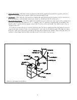
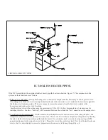
Page 15: ...15 14 FIGURE12 INDIRECTWATERHEATER BOILERSIDEPIPING FIGURE11 STANDARDBOILERPIPING...

Page 16: ...g for a gravity hot water boiler The circulator 1 1 2 x 2 bushings and 1 1 2 piping are removed and the system piping is run directly to the 2 supply and return tappings on the boiler If isolation val...

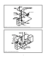
Page 17: ...17 FIGURE15 BOILERPIPINGWITHCHILLER FIGURE14 ISOLATIONOFBOILERFROMSYSTEMWITHAHEATEXCHANGER 16...

Page 18: ...ting range of approximately 110 to 130F Follow the manufacturer s instructions for installing this valve Usually a heat trap will be required between the coil and the hot connection on the mixing valv...

Page 19: ...boiler Install unions anywhere in the tankless heater piping that will facilitate removal of the heater 7 Backflow Preventer Required in Massachusetts If required by local codes install a backflow pr...

Page 20: ...spots near any heat source or in direct sunlight cold spots outside walls walls adjacent to unheated areas locations subject to drafts Provide Class II circuit between thermostat and boiler Connect t...

Page 21: ...ESS IS REPLACED WITH JUMPER PLUG TH TR ROBERTSHAW 7000DERHC GAS VALVE CWI379 HONEYWELL VR8204 VR8304 SERIES GAS VALVES CWI069 345 2 NOTE 2 2 VENT DAMPER REQUIRED ON ALL BOILERS EXCEPT CWI310 CWI379 WH...

Page 22: ...used for other 24 volt zone valves as long as they are equipped with end switches Do not attempt to use the transformer on the limit control to power the zone valves use a separate transformer Up to...

Page 23: ...23 22 FIGURE23 ZONEWIRINGUSINGHONEYWELLV8043FZONEVALVES FACTORYWIRINGNOTSHOWN SEE FIGURES18 21 FIGURE22 CIRCULATORZONEWIRINGUSINGHONEYWELLR845As FACTORYBOILERWIRING NOTSHOWN SEE FIGURES 18 21...

Page 24: ...ition the damper will close 2 If the boiler water temperature is less than the low limit setting minus the differential setting terminals R and B in the L8124E are made through the low limit switch Th...

Page 25: ...mperature is less than the low limit setting minus the differential setting terminals R and B in the L8124E are made through the low limit switch The low limit switching action is SPDT with R being co...

Page 26: ...THE BOILER UNDERWENT THE TESTS SPECIFIED IN Z21 13 25 Safety Control Operation Standing Pilot and Intermittent Ignition High Limit Interrupts main burner operation when the supply water temperature e...

Page 27: ...26 No yellow tipping should be present however intermittent flecks of yellow and orange in theflamearenormal 12 Check entire gas train for leaks using soap and water or other approved leak detection...

Page 28: ...ct a manometer to the manifold outlet pressure tap on the gas valve see Figures 27 and 28 d Read the manifold pressure It should be set at NaturalGas LPGas Manifold Press inches w c 3 5 10 0 e If a ma...

Page 29: ...ncrease to hi limit setting The burners should shut down and the circulator continue running For standing pilot boiler models pilot burner should remain lit but the main burners should stop firing For...

Page 30: ...light pilot burner with a match After about one minute release reset button Pilot should remain lit If it goes out turn gas control knob clockwise to OFF To relight repeat steps 5 9 If button does no...

Page 31: ...old the Knob while you light pilot burner with a match After about one minute release reset button Pilot should remain lit If it goes out turn gas control knob clockwise to OFF To relight repeat steps...

Page 32: ...all electric power to the appliance 4 This appliance is equipped with an ignition device which automatically lights the pilot Do try to light the pilot by hand not 5 Remove front access panel 6 Rotat...

Page 33: ...lowest setting 3 Turn off all electric power to the appliance 4 This appliance is equipped with an ignition device which automatically lights the pilot Do try to light the pilot by hand not 5 Remove f...

Page 34: ...ANDVR8304 INTERMITTENT IGNITION FIGURE 27a GASVALVEDETAIL HONEYWELLVR8200ORVR8300 STANDINGPILOT FIGURE 27b GASVALVEDETAIL ROBERTSHAW 7000ERHCANDHONEYWELLV8295 STANDINGPILOT FIGURE 28b GASVALVEDETAIL R...

Page 35: ...ounding strap The ideal gap between the electrode and the ground strap is 1 8 Inspect the porcelain for cracks or other deterioration Replace pilot assembly if deterioration is found 6 Inspect the com...

Page 36: ...the pilot main burner in its original location 16 Replace the blocked vent switch 17 Reconnect the damper and vent system WARNING SOOT DEPOSITS IN THE FLUE PASSAGES ARE A SIGN THAT THE BOILER MAY BE...

Page 37: ...f voltage is present the damper is defective or there is an obstruction in the path of the damper blade If no voltage is present there is either a loose connection in the damper harness or the limit c...

Page 38: ...d sw itch w iring Defective t stat or zone valve end sw itch T stat or zone system misw ired consult t stat or zone valve manufacturer s instructions Vent damper open 24 volts across B and R limit sw...

Page 39: ...raft Inadequate combustion air supply in boiler room Y N N Y Y 24 volts across rollout sw itch Loose electrical connection in 24 volt w iring betw eenB1 or B2 and gas valve or module Rollout sw itch o...

Page 40: ...itch and B2 Y Refer to standing pilot or intermittent ignition troubleshooting chart page 41 or 42 START Defective damper Defective damper harness Loose damper harness connection Obstruction in path...

Page 41: ...nt T stat or zone system misw ired consult t stat or zone valve manufacturer s instructions N Do burner and circulator shut dow n at end of call for heat END Pull w ire off of T terminal on aquastat D...

Page 42: ...orifice partially plugged Y N N Y N Turn control on gas valve to ON Y END Defective gas valve Y START 24 VOLTS PRESENT ACROSS TH AND TR ON GAS VALVE BUT MAIN BURNERS DO NOT LIGHT Ensure knob on gas v...

Page 43: ...rcelain cracked Pilot flame not covering gap between electrode and grounding strap Low gas pressure at gas valve inlet Defective S8600 module Main burner lights N Y 24VAC across terminals 1 2 on S8600...

Page 44: ...1 2 SELF TAPPING SCREW 900100 20 ea 20 ea 20 ea 20 ea 21 ea 21 ea 21 ea 21 ea 25 ea 25 ea 11 1 2 x 2 SEALING STRIP 900146 3 7 ft 4 2 ft 4 8 ft 5 3 ft 5 9 ft 6 4 ft 7 0 ft 7 5 ft 8 0 ft 8 5 ft 12 ROLL...

Page 45: ...45 44...

Page 46: ...0 043 900041 900041 900041 49 35 1600 392449 50 35 1650 392449 4 51 51 51a 51 51a 61 40mm BURNER LESS PILOT BRACKET 150541 1 ea 2 ea 3 ea 4 ea 5 ea 6 ea 7 ea 8 ea 62 MANIFOLD 40mm BURNERS 1 ea 701253...

Page 47: ...47 46...

Page 48: ...3 96 033 96 035 96 035 96 036 96 036 89 3 4 SHORT WELL LESS COIL BOILERS 35 1010 1 ea 1 ea 1 ea 1 ea 1 ea 1 ea 1 ea 1 ea 1 ea 1 ea 89 3 4 LONG WELL WITH COIL BOILERS 35 1020 1 ea 1 ea 1 ea 1 ea 1 ea 1...

Page 49: ...49 48...

Page 50: ...e care not to disturb the ceramic fiber gasket 2 Once the heat exchanger has been placed on the base inspect the gasket for proper seal Repair or replace gasket if necessary 3 Secure the heat exchange...

Page 51: ...51 50 FIGUREA1 BASE HEATEXCHANGER FLUE COLLECTORASSEMBLY...

Page 52: ...emovable door g Rating Plate Located on the upper left of the right side panel D GasValveInstallation 1 The gas valve assembly has been pre piped with one half of a piping union and is to be connected...

Page 53: ...53 52 FIGUREA2 JACKETINSTALLATION...

Page 54: ...ide redundancy This valve should be factory pre wired to the 7000ERHC with one black lead connected to the TH terminal and the other black lead connected to the TR terminal on the 7000ERHC gas valve 5...

Page 55: ...55 54 FIGUREA3 TAPPING LOCATIONS SEE TEXT FOR TAPPING USES...

Page 56: ...56 Tel 215 535 8900 Fax 215 535 9736 www crownboiler com Manufacturer of Hydronic Heating Products P O Box 14818 3633 I Street Philadelphia PA 19134...

Reviews: