


30
A. This appliance has a pilot which must be
lighted by hand. When lighting the pilot, follow
these instructions exactly.
B. BEFORE LIGHTING smell all around the
appliance area for gas. Be sure to smell next
to the floor because some gas is heavier than
air and will settle on the floor.
WHAT TO DO IF YOU SMELL GAS
Do not try to light any appliance.
Do not touch any electric switch; do not
use any phone in your building.
Immediately call your gas supplier from
a neighbor’s phone. Follow the gas
supplier’s instructions.
If you cannot reach your gas supplier, call
the fire department.
C. Use only your hand to push in or turn the gas
control knob. Never use tools. If the knob will
not push in or turn by hand, don’t try to repair it,
call a qualified service technician. Force or
attempted repair may result in a fire or explosion.
D. Do not use this appliance if any part has been
under water. Immediately call a qualified service
technician to inspect the appliance and to
replace any part of the control system and any
gas control which has been under water.
LIGHTING INSTRUCTIONS
1. STOP! Read the safety information above on
this label.
2. Set the thermostat to lowest setting.
3. Turn off all electric power to the appliance.
4. Remove front access panel.
5. Rotate the gas control knob clockwise to OFF.
8. Turn Knob on gas control counterclockwise
to “PILOT”.
9. Push down and hold the red reset button while
you light pilot burner with a match.
After about one minute, release reset button.
Pilot should remain lit. If it goes out, turn gas
control knob clockwise to OFF. To relight,
repeat steps 5-9.
If button does not pop up when released, stop
and immediately call your service technician
or gas supplier.
If the pilot will not stay lit after several tries,
turn the gas control knob to “OFF” and call
your service technician or gas supplier.
10. After pilot remains lit when red reset button is
released, turn gas control knob counterclockwise
to ON.
11. Replace front access panel.
12. Turn on all electric power to the appliance.
13. Set thermostat to desired setting.
1. Set the thermostat to lowest setting.
2. Turn off all electric power to the appliance if
service is to be performed.
3. Push in gas control knob slightly and turn
clockwise to “OFF”. Do not Force.
WARNING: If you do not follow these instructions exactly, a fire or explosion
may result causing property damage, personal injury or loss of life.
6. Wait five (5) minutes to clear out any gas. Then
smell for gas, including near the floor. If you then
smell gas, STOP! Follow “B” in the safety inform-
ation above on this label. If you don’t smell gas,
go to the next step.
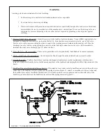
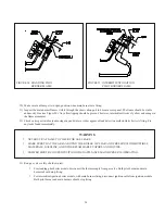
7. Find pilot - follow metal pilot
tube from gas control to
pilot burner.
146-80-254 Rev. 0
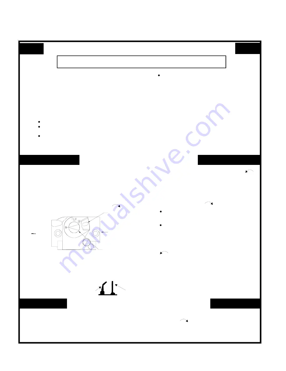
(Standing Pilot)
PILOT
BURNER
THERMO-
COUPLE
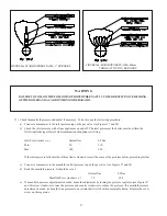
TO TURN OFF GAS TO APPLIANCE
FOR YOUR SAFETY READ BEFORE OPERATING
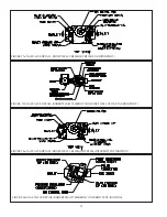
RESET BUTTON
GAS INLET
GAS CONTROL KNOB
(SHOWN IN “ON” POSITION)
GAS OUTLET
GAS VALVE - TOP VIEW
LIGHTING INSTRUCTIONS FOR BOILERS EQUIPPED WITH HONEYWELL
VR8200 AND VR8300 SERIES GAS VALVES (STANDING PILOT)
29
Summary of Contents for CWI Series
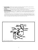
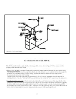
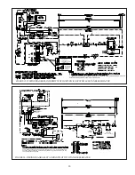
Page 15: ...15 14 FIGURE12 INDIRECTWATERHEATER BOILERSIDEPIPING FIGURE11 STANDARDBOILERPIPING...
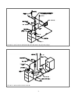
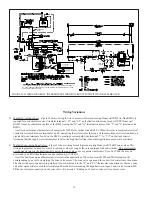
Page 17: ...17 FIGURE15 BOILERPIPINGWITHCHILLER FIGURE14 ISOLATIONOFBOILERFROMSYSTEMWITHAHEATEXCHANGER 16...
Page 45: ...45 44...
Page 47: ...47 46...
Page 49: ...49 48...
Page 51: ...51 50 FIGUREA1 BASE HEATEXCHANGER FLUE COLLECTORASSEMBLY...
Page 53: ...53 52 FIGUREA2 JACKETINSTALLATION...
Page 55: ...55 54 FIGUREA3 TAPPING LOCATIONS SEE TEXT FOR TAPPING USES...


