18
18
IX TANKLESS HEATER PIPING
If the CWI is supplied with a tankless heater, pipe the heater as shown in Figure 17. The components in this system and
their functions are as follows:
1) Mixing Valve (Required) - During the heating season, the water exiting the tankless heater may be 180 degrees or more.
The mixing valve blends hot water leaving the tankless heater with cold water so as to maintain the hot water supplied
to the fixtures at a fixed temperature. This saves energy, increases the amount of usable hot water available to the
homeowner, and reduces the risk of scalding.
Install a mixing valve with a setting range of approximately 110 to 130F. Follow the manufacturer’s instructions for
installing this valve. Usually a “heat trap” will be required between the coil and the “hot” connection on the mixing valve.
2) Flow Restrictor (Recommended) - If water is drawn from the tankless coil at a rate in excess of the rating in Table 1,
the temperature of the hot water may be too low to be of use. The use of a flow restrictor will prevent this problem by
limiting the rate at which water can pass through the tankless heater. If a restrictor is used, select one having a rating in
GPM approximately equal to the rating shown in Table 1. If possible, locate this restrictor at least 3 feet from the tankless
heater inlet so that it is not subjected to excessive temperatures when no water is flowing through the coil.
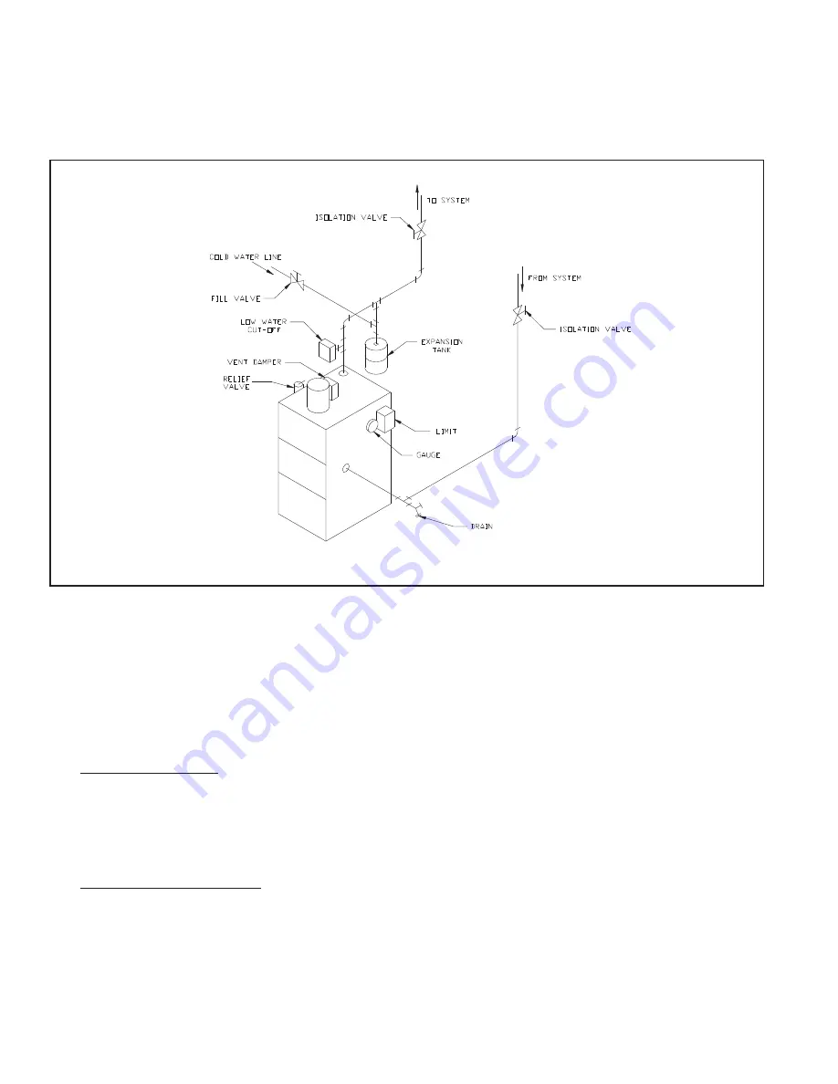
FIGURE 16: GRAVITY PIPING
Summary of Contents for CWI103
Page 2: ......
Page 17: ...15 15 FIGURE 12 INDIRECT WATER HEATER BOILER SIDE PIPING FIGURE 11 STANDARD BOILER PIPING ...
Page 34: ...32 32 Notes ...
Page 41: ...39 39 Notes ...
Page 43: ...41 41 ...
Page 45: ...43 43 ...
Page 47: ...45 45 ...
Page 49: ...47 47 FIGURE A1 BASE HEAT EXCHANGER FLUE COLLECTOR ASSEMBLY ...
Page 51: ...49 49 FIGURE A2 JACKET INSTALLATION ...
Page 53: ...51 51 FIGURE A3 TAPPING LOCATIONS SEE TEXT FOR TAPPING USES ...
Page 54: ...52 52 Notes ...
Page 55: ...53 53 Notes ...


