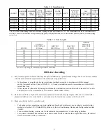
background image


Series


!"##"!$"$%&"!!&'!$


!()(* +,*

((-

./

0

PHNTM080

0

PHNTM100

0

PHNTM120

0

PHNTM150

0

PHNTM180

"&

: Improper installation, adjustment, alteration, 

service or maintenance can cause property damage, injury, 
or loss of life. For assistance or additional information, con-


Manufacturer of Hydronic Heating Products

P.O. Box 14818  3633 I. Street

Philadelphia, PA  19134

www.crownboiler.com

46794:6;4:<4;

9700609

Summary of Contents for PHNTM080

Page 1: ...lation adjustment alteration service or maintenance can cause property damage injury or loss of life For assistance or additional information con Manufacturer of Hydronic Heating Products P O Box 1481...

Page 2: ......

Page 3: ...t or component failure will prevent your boiler from lighting In winter your pipes may freeze and cause extensive property damage Do not leave the heating system unattended during cold weather unless...

Page 4: ...0 B D A B 0 B B A B B B B B B A A B B F F A 0 B B A 0 B B A D A 0 B A B B B A A E 0 B A A BB BB BB B B B 0 BB A A B B B G BB B B A B A 0 A B B B B B B A B B A D B B A B A B B B B B A B B 0 B B A F B A...

Page 5: ...39 F Assembly of DuraVent PolyPro Vent Systems 46 I Condensate Trap and Drain 59 J Removing An Existing Boiler From Common Chimney 60 VIII Gas Piping 62 IX System Piping 64 A General System Piping Pr...

Page 6: ...ustion air supplied from outdoors It is not designed for use in gravity hot water systems or systems A SEE TABLE 2 3 16 5 8 CONNECTION SUPPLY WATER RETURN WATER PRESSURE GAUGE OUTSIDE INSIDE OF WALL C...

Page 7: ...0 2 12 60ft 9 080 3 12 135ft 2 100 2 12 60ft 15 100 3 12 135ft 3 120 3 12 135ft 7 150 3 52 135ft 7 180 3 52 135ft 9 See Part VII Venting for additional requirements and details III Before Installing 1...

Page 8: ...cess to the front of the boiler is provided through a door b Access is provided to the condensate trap located beneath the boiler 3 Observe the following clearances from piping to combustible construc...

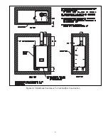
Page 9: ...7 Figure 4 1 Minimum Clearances To Combustible Construction...

Page 10: ...he boiler is mounted is plumb 4 Before mounting the boiler make sure that wall selected does not have any framing or other construction that will interfere with the vent pipe penetration use Figure 5...

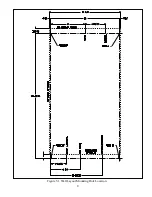
Page 11: ...9 Figure 5 1 Wall Layout Mounting Hole Location...

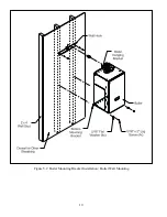
Page 12: ...10 Figure 5 2 Boiler Mounting Bracket Installation Boiler Wall Mounting...

Page 13: ...11 VI Air for Ventilation Air for combustion must always be obtained directly from outdoors See Section VII for intake piping Adequate air for tion manual or applicable code B B F A B B B A B B B...

Page 14: ...7 21 Q Horizontal Side Wall Concentric Venting Figure 7 0d The entire vent system is concentric from the boiler to the termination on the wall The venting components used in this system are available...

Page 15: ...13 FIGURE 7 0 BASIC VENT OPTIONS FIGURE 7 0a HORIZONTAL TWIN PIPE FIGURE 7 0b VERTICAL TWIN PIPE FIGURE 7 0c SPLIT VENTING FIGURE 7 0d e HORIZONTAL VERTICAL CONCENTRIC VENTING...

Page 16: ...Air Intake Lengths The maximum length of the vent air intake piping depends upon the vent option selected and the boiler size See Tables 7 5 7 13 or 7 21 for the maximum vent lengths These maximum le...

Page 17: ...of Horizontal Vent Piping Pitch all horizontal vent piping so that any condensate which forms in the piping will run towards the boiler Q Q _ A Y 4 Y 49 Y 4 A A Y 4 Y 49 Y 4 TABLE 7 1 VENT AIR INTAKE...

Page 18: ...p must be provided Figures 7 3a 7 3b When a straight horizontal run of pipe exceeds 20ft and is restrained at one end with an elbow at the other avoid putting a hanger or _ are not permitted Q Part VI...

Page 19: ...17 FIGURE 7 3 EXPANSION LOOPS FOR CPVC PVC PIPE FIGURE 7 3b FIGURE 7 3a FIGURE 7 3c FIGURE 7 4 WALL PENETRATION CLEARANCES FOR PVC VENT PIPE...

Page 20: ...s _ This terminal is shown in Figure 7 7 If the terminal is oriented vertically alternate orientation shown in Fig 7 7 the exhaust opening must be on the top as shown See Part VII E of this manual and...

Page 21: ...12B or 3PPS 36B w Screen 2PF 10UV or 2PF 39UV w Screen 3PF 10UV or 3PF 39UV w Screen ISEP02 or ISEP0239 w Screen ISEP03 or ISEP0339 w Screen Intake Elbow w Screen Note 3 Elbow w Screen Note 3 Elbow w...

Page 22: ...l must be at least 7 feet above a public walkway Q Do not install the vent terminal directly over windows or doors Q The bottom of the vent terminal must be at least 3 feet above any forced air inlet...

Page 23: ...FIGURE 7 7 HORIZONTAL CPVC PVC VENTING WITH LOW PROFILE TERMINAL VENT OPTIONS 1 2 TERMINAL OPTIONS B C FIGURE 7 8 HORIZONTAL CPVC PVC WITH CONCENTRIC VENT TERMINAL VENT OPTIONS 1 2 TERMINAL OPTIONS D...

Page 24: ...AVENT POLYPRO SELKIRK POLYFLUE OR CENTROTHERM INNOFLUE HORIZONTAL VENTING VENT OPTIONS 3 8 TERMINAL OPTION A FIGURE 7 10 DURAVENT POLYPRO HORIZONTAL VENTING WITH CONCENTRIC TERMINAL VENT OPTIONS 3 4 T...

Page 25: ...ELATIVE TO WINDOWS DOORS GRADE FIGURE 7 11b LOCATION OF VENT TERMINAL RELATIVE TO METERS AND FORCED AIR INLETS FIGURE 7 11c POSITIONING VENT TERMINAL UNDER OVERHANGS Max X in Min Y in 36 60 12 12 18 2...

Page 26: ...or both terminations Two rodent screens suitable for 3 PVC terminals _ Size Vent System Rodent Screen Bird Guard 2 Polypro DuraVent 2PPS BG 3 Polypro DuraVent 3PPS BG 2 InnoFlue Centrotherm IASPP02 3...

Page 27: ...t 135ft Terminal Option H Fittings Vent Coupling w Screen Coupling w Screen 2PPS 12B or 2PPS 36B w Screen 3PPS 12B or 3PPS 36B w Screen 2PF 10UV or 2PF 39UV w Screen 3PF 10UV or 3PF 39UV w Screen ISEP...

Page 28: ...3 Min B Vent ID 5 6 5 6 Min Equivalent Vent Length Models 080 36 36 36 36 100 36 36 36 36 120 Not Permitted 36 Not Permitted 36 150 52 52 180 52 52 Max Equivalent Vent Length Note 1 Models 080 60ft 1...

Page 29: ...Part VII D for additional details Q Q _ Bends used to make these offsets may not exceed 45 degrees Q termination is not counted If offsets described above are present the equivalent length of the ben...

Page 30: ...ex Pipe Equivalent Length ft Flex Vent 1 ft 2 DuraVent PolyPro Flex 2 0 ft 2 0 ft 2 0 ft 3 DuraVent PolyPro Flex 2 0 ft 2 3 ft 2 3 ft B Vent Air Chase 1ft 2 Flex Vent in 5 or larger B Vent 1 0 ft 3 Fl...

Page 31: ...29 FIGURE 7 15 VERTICAL CPVC PVC VENTING VENT OPTIONS 10 11 TERMINAL OPTION H FIGURE 7 16 VERTICAL CPVC PVC VENTING WITH IPEX CONCENTRIC VENT TERMINAL VENT OPTIONS 10 11 TERMINAL OPTIONS I J...

Page 32: ...OLYPRO VERTICAL VENTING WITH CONCENTRIC TERMINAL VENT OPTIONS 12 13 TERMINAL OPTION K FIGURE 7 17 DURAVENT POLYPRO SELKIRK POLYFLUE OR CENTROTHERM INNOFLUE VERTICAL SINGLE WALL PP VENTING VENT OPTIONS...

Page 33: ...31 FIGURE 7 20 CENTROTHERM INOFLUE B VENT AIR CHASE SYSTEM VENT OPTIONS 20 21 FIGURE 7 19 DURAVENT POLYPRO B VENT AIR CHASE SYSTEM VENT OPTIONS 18 19...

Page 34: ...tions shown in Tables 7 21 terminate in a PVC 90 sweep elbow pointing down Use of a rodent screen is generally recommended for the intake termination A rodent screen suitable for 3 PVC terminals is su...

Page 35: ...ngth First elbow is ignored The terminal is also ignored From Table 7 14 the equivalent length of 3 DuraVent Poly Pro Flex is 2 0ft From Table 7 1 the equivalent length of the second 90 elbow is 8 7ft...

Page 36: ...60ft 135ft 60ft 135ft 100 60ft 135ft 60ft 135ft 60ft 135ft 120 Not Permitted 135ft Not Permitted 135ft 135ft 150 135ft 135ft 135ft 180 135ft 135ft 135ft Rigid Vent Terminals Vent Coupling w Screen Cou...

Page 37: ...52 52 52 52 52 52 52 Max Equivalent Vent Length Note 1 60ft 135ft 60ft 135ft 60ft 135ft 60ft 135ft 60ft 135ft 60ft 135ft 60ft 135ft 60ft 135ft 135ft 135ft 135ft 135ft 135ft 135ft 135ft 135ft 135ft 135...

Page 38: ...36 FIGURE 7 23 SPLIT VENT SYSTEM FLEX IN B VENT CHASE VENT OPTIONS 33 38 FIGURE 7 22 SPLIT RIGID VENT SYSTEM VENT OPTIONS 25 32 CPVC SYSTEM SHOWN IN ABOVE EXAMPLE...

Page 39: ...37 FIGURE 7 24 SPLIT VENT SYSTEM FLEX IN ABANDONED MASONRY CHIMNEY VENT OPTIONS 33 38...

Page 40: ...38 Venting of Other Appliances Or Fireplace into Chase or Adjacent Flues Prohibited FIGURE 7 25 MASONRY CHIMNEY CHASE REQUIREMENTS...

Page 41: ...ide diameters The larger upper inside diameter accepts 3 CPVC pipe and _ A locking ring in the adaptor prevents the vent pipe from coming out of the adaptor once it is inserted Lubricate bottoms out e...

Page 42: ...as the vent system except as follows a into the air intake connection and drill a 1 8 tap hole into the PVC which lines up with the 7 32 clearance hole and secure them together with a 10 x 1 sheet me...

Page 43: ...41 FIGURE 7 29 INSTALLATION OF STANDARD VERTICAL TERMINALS FIGURE 7 28 INSTALLATION OF STANDARD HORIZONTAL TERMINALS...

Page 44: ...ews b Drill two 3 1 8 holes through the wall for the vent and intake pipes c Drill four 3 16 holes for the mounting screws d Install the vent and intake pipe sections passing through the wall Cut the...

Page 45: ...43 FIGURE 7 31 INSTALLATION OF DIVERSITECH LOW PROFILE TERMINAL THROUGH SIDEWALL FIGURE 7 30 INSTALLATION OF IPEX LOW PROFILE TERMINAL THROUGH SIDEWALL...

Page 46: ...44 FIGURE 7 33 INSTALLATION OF IPEX AND DIVERSITECH CONCENTRIC TERMINAL THROUGH SIDEWALL FIGURE 7 32 CUTTING IPEX AND DIVERSITECH CONCENTRIC VENT TERMINALS...

Page 47: ...the gap between the OD of the outer pipe and the exterior side of the wall with RTV sealant h Cement the rain cap onto the inner pipe If desired the rain cap can be attached to the inner pipe with the...

Page 48: ...out of the adaptor once it is inserted adaptor until it bottoms out b _ DuraVent 3PPS R2 Otherwise assemble the next piece of 3 Polypro c For each joint verify that the gasket is evenly seated in the...

Page 49: ...g towards the outside 4 Installation of Horizontal Fitting Terminals Terminal Option A a See Figure 7 36 for proper orientation of twin pipe horizontal terminals Outer edge of exhaust coupling must be...

Page 50: ...48 FIGURE 7 36 INSTALLATION OF DURAVENT POLYPRO UV RESISTANT SINGLE WALL HORIZONTAL TERMINAL FIGURE 7 37 INSTALLATION OF DURAVENT POLYPRO UV RESISTANT SINGLE WALL VERTICAL TERMINAL...

Page 51: ...orient the termination so the air intake slots face down The cap must be installed level or sloped 1 8 per foot away from the appliance e Seal the termination to the exterior wall plate with weather r...

Page 52: ...50 FIGURE 7 40 INSTALLATION OF DURAVENT POLYPRO CONCENTRIC TERMINAL THROUGH ROOF FIGURE 7 39 INSTALLATION OF DURAVENT POLYPRO CONCENTRIC VENT TERMINAL THROUGH SIDEWALL...

Page 53: ...thread adaptor 2 or 3 depending on the Vent Option Cut a clearance hole in the cap for the male threads Secure the adaptor to the cap using a 2 or 3 electrical conduit lock nut Seal all joints with R...

Page 54: ...er edge of exhaust coupling must be 10 or less from the wall surface Figure 7 9 b Remove the gasket from the end of the integral exhaust coupling and insert Selkirk 2PF HVST or 3PFHVST in its place c...

Page 55: ..._ the same manufacturer will also be required for the run from the boiler to the base of the chimney B C C A B 0 C C B B B B 0 C C 7 0 F F C A F F A BB A FIGURE 7 41 POLYFLUE PIPE LOCKING BAND INSTALL...

Page 56: ...54 FIGURE 7 42 INSTALLATION OF SELKIRK POLYFLUE UV RESISTANT SINGLE WALL HORIZONTAL TERMINAL FIGURE 7 43 INSTALLATION OF SELKIRK POLYFLUE UV RESISTANT SINGLE WALL VERTICAL TERMINAL...

Page 57: ...this gasket with Centrocerin IACE50 Slide a connector ring over the male end of the pipe to be joined as shown in Figure 7 44 Push the male end of the next section of pipe into the bell until it bott...

Page 58: ...urface Figure 7 5 b Use plain end UV stabilized Centrotherm 2 pipe ISEP02 or ISEP0239 or 3 pipe ISEP03 or ISEP0339 and insert Centrotherm Bird Screen IASPP02 or IASPP03 in the end of the pipe c Add PV...

Page 59: ...57 FIGURE 7 45 INSTALLATION OF CENTROTHERM INNOFLUE UV STABILIZED SINGLE WALL HORIZONTAL TERMINAL FIGURE 7 46 INSTALLATION OF CENTROTHERM INNOFLUE UV STABILIZED SINGLE WALL VERTICAL TERMINAL...

Page 60: ...d When Vent Options 20 21 are used install a Tee of the same size at the base of the vent Route the smooth section of InnoFlue Flex 3 or Flex Adaptor 2 through a cap in the base of this Tee Use a Cen...

Page 61: ...ler into the end of the extension as shown in Figure 7 47 2 through areas that could be damaged by leaking condensate 3 Some jurisdictions may require that the condensate be neutralized before being d...

Page 62: ...g connected to the common venting system are located and other spaces of the building Turn on clothes dryers and any appliance not connected to the common venting system Turn on any exhaust fans such...

Page 63: ...61 This page is intentionally left blank...

Page 64: ...stream from manual shut off valve must be electrically continuous and bonded to a grounding electrode Refer to National Electrical Code NFPA 70 The boiler and its gas connection must be leak tested be...

Page 65: ...B B B B BB B FIGURE 8 1 GAS CONNECTION TO BOILER TABLE 8 2 MINIMUM AND MAXIMUM INLET PRESSURES MODEL MAX NATURAL LP MIN NATURAL MIN LP 080MBH 14 0 2 5 11 0 100MBH 14 0 2 5 11 0 120MBH 14 0 2 5 11 0 15...

Page 66: ...requent additions of make up water can expose the heat exchanger to oxygen on a continuous basis In addition frequent additions of hard make up water can cause calcium deposits to collect in the heat...

Page 67: ...13 3 180MBH 9 3 13 3 Method 1 Primary Secondary Piping Strongly Recommended This method can be used in heat only applications as shown in Figure 9 2 or with an indirect water heater as shown _ _ as yo...

Page 68: ...66 FIGURE 9 2 PIPING METHOD 1 NEAR BOILER PIPING HEATING ONLY...

Page 69: ...67 FIGURE 9 3A PIPING METHOD 1 NEAR BOILER PIPING HEATING PLUS INDIRECT WATER HEATER IWH OFF PRIMARY LOOP...

Page 70: ...68 FIGURE 9 3B PIPING METHOD 1 NEAR BOILER PIPING HEATING PLUS INDIRECT WATER HEATER IWH OFF BOILER LOOP...

Page 71: ...ffective connection points for automatic air elimination devices and an expansion tank These separators are available from several sources and may be used in place of the closely spaced tees shown in...

Page 72: ...70 FIGURE 9 6 PIPING METHOD 1 NEAR BOILER PIPING SHADED BOILER LOOP...

Page 73: ...one advantage to this method is its installation simplicity It may make sense to use this method when the boiler is to be installed with a new single zone system having a low pressure drop Figure 9 8...

Page 74: ...ft wc Fig9 8b Models with Grundfos 26 99 Speed 3 Do not Use Speeds 1 or 2 FIGURE 9 8b GRUNDFOS NET CIRCULATOR PERFORMANCE CURVE Flow GPM Available Head ft Models with Taco 0013 FIGURE 9 8a TACO NET CI...

Page 75: ...isgaugeisshippedloose Installitasshown in Figure 9 9 3 Circulator required The boiler loop circulator is factory installed inside the boiler cabinet Usually at least one addition circulator not suppli...

Page 76: ...t X Install the low water cut off in the supply piping at the point prescribed the local jurisdiction generally at a point above the boiler If a probe type low water cut off is used be certain that it...

Page 77: ...10 Consult the heat exchanger manufacturer for proper heat exchanger sizing as well as expansion tank must be designed for use in oxygenated water 2 Piping with a Chiller If the boiler is used in conj...

Page 78: ...nded and is required by many local codes Locate this switch in accor dance with local codes or in the absence of any in a location where it can be safely accessed in an emergency involving the boiler...

Page 79: ...closely spaced tees or by a hydraulic separator The system pump is always on when the system is responding to a call b DHW Pump IWH Circulator Pumps water directly through the indirect water heater M...

Page 80: ...78 FIGURE 10 2 HIGH VOLTAGE PCB TERMINAL CONNECTIONS FIGURE 10 3 LOW VOLTAGE PCB TERMINAL CONNECTIONS...

Page 81: ...ations where the sensor will pick up direct radiation from the sun should also be avoided Avoid placing the sensor the boiler using 22 gauge or larger wire As with the sensor itself the sensor wiring...

Page 82: ...80 FIGURE 10 4 PROPER INSTALLATION OF HEADER SENSOR...

Page 83: ...me Rod P8 9 P8 8 P3 3 L3 1 J4 4 J4 2 J4 6 J4 3 J4 5 J4 7 Combustion Fan 120V Conn 1 3 2 F1 6 3A Slow Blow P3 10 P3 11 P3 7 P3 12 J8 10 J8 4 J8 9 J8 8 J8 11 J8 5 J10 7 J10 8 P10 1 P10 3 Header Sensor O...

Page 84: ...82 FIGURE 10 6 INTERNAL WIRING CONNECTIONS DIAGRAM...

Page 85: ...83...

Page 86: ...stem to at least 12 psi at the boiler 6 Bleed air from the heat exchanger using the manual air vent in the top left side of the heat exchanger Figure 11 1 To do this install a piece of ID clear tubing...

Page 87: ...d the use of petroleum based boiler additives These can attack seals in both the boiler and system K R 5 S U E J V S G J Z HH S S JS EDL C L HH E R K E R E Z R R Many of these products require annual...

Page 88: ...spark lasting approximately 4 seconds and an audible click for ignition it will enter a soft lockout and will wait for one hour before attempting another ignition sequence This soft 13 _Figure 11 2c T...

Page 89: ...87 FIGURE 11 3 BURNER FLAME FIGURE 11 2a HOME SCREEN AT POWER UP No Call for Heat FIGURE 11 2b HOME SCREEN ON HEAT DEMAND FIGURE 11 2c HOME SCREEN WITH ACTIVE FAULT PHNTM080 PHNTM080 PHNTM080...

Page 90: ...88 FIGURE 11 4a GAS VALVE DETAIL 80MBH THRU 120MBH FIGURE 11 4b GAS VALVE DETAIL 150MBH 180MBH B B A A D B B B B A A B B B I J B B B A B F B B A A B B B I J B...

Page 91: ...will a period of time which varies depending on which screen is open From the manual input screen it takes 12min 45s 2 and O2 readings are shown in Table 11 5 Final readings should be taken with all...

Page 92: ...90 Lighting and Operating Instructions...

Page 93: ...iler Q DHW pump Q System pump Refer to the Piping Section for the location of these pumps The touch screen display on this boiler has three basic functions 1 To allow the professional HVAC technician...

Page 94: ...SED UNLESS AT LEAST ONE OF THE FOLLOWING CONDITIONS IS TRUE An external energy management system is installed that reduces the boiler water temperature as the heating load decreases This boiler is not...

Page 95: ...a call from the heating thermostat if the outdoor temperature is warm WWSD Disabled The boiler will always respond to a call for heat regardless of the outdoor temperature WWSD Enabled When the outdo...

Page 96: ...del Options x PHNTM080 S L 2000ft x PHNTM100 S L 2000ft x PHNTM120 S L 2000ft x PHNTM150 S L 2000ft x PHNTM180 S L 2000ft DHW System Pump Options x Option 1 System pump runs for CH only DHW priority p...

Page 97: ...ssive temperatures Option 2 System Pump Used for CH Only No DHW Priority Pumping An example of this system is shown in Figure 12 2 as well as in Figures 9 3A and 9 3B The only difference between Optio...

Page 98: ...96 FIGURE 12 2 PIPING FOR DHW OPTIONS 1 2 ALSO SEE FIGURES 9 3A 9 3B FIGURE 12 3 PIPING FOR DHW OPTION 3...

Page 99: ...gain give priority to the DHW temperature when either of the following events occur Q The call for CH ends Q The call for DHW is removed and then restored Regardless of the DHW option selected the tar...

Page 100: ...less of how high the outdoor temperature is Max Outdoor Temp At or above this setting supply setpoint is equal to the Min Supply Setpoint Min Outdoor Temp At or below this setting supply setpoint is e...

Page 101: ...99 FIGURE 12 5 SETTINGS MENU SEE PART C FOR ADDITIONAL INFORMATION...

Page 102: ...mplished using the thermostat on the storage type indirect water heater 4 Manual Input From the settings menu press the MANUAL INPUT button to temporarily lock the boiler into either high or _ by pres...

Page 103: ...to quickly identify how the boiler is currently 1 Home Screen a Current Demand The demand to which the boiler is currently responding If more than one demand is present the Current Demands shown will...

Page 104: ...rarily Save Field and Exit Backspace Exit Screen without Saving Clear Entire Field 1 Touch field to be changed 2 Screen below will appear Use appropriate keys to enter first line How to Enter Service...

Page 105: ...al Burner Status include Standby Burner is not needed because there is no call for heat or the target temperature has been reached Standby Delay Burner is needed but is being temporarily held off gene...

Page 106: ...104 ODR Status Screens Only Visible if Outdoor Reset is Enabled in Configuration Menu PHNTM080 FIGURE 12 8 STATUS MENU SEE PART E FOR ADDITIONAL INFORMATION...

Page 107: ...t mode see Settings Menu d Modulation Source Should always read Local Mod Control in the applications covered by this manual 6 Pump Status a Boiler Indicates whether the boiler pump is currently power...

Page 108: ...F C A A B A B B BB B B A 0 B A F B A A A B A 0 A B F B A 0 B B 0 0 A B B 0 A B B B B 0 B B B B B B F A 0 B A F B 0 A B B B B B B A B B A D B B A B A B B B B B A B B 0 B B A F B A B B B D B A F BB 0 B...

Page 109: ...and gas lines to verify they are free from leaks Call the service technician to make repairs if required 4 Annual Inspections and Service In addition to the inspections listed above the following sho...

Page 110: ...THIS NUT TO WHEN DISCONNECTING FLEXIBLE GAS LINE FLEXIBLE GAS LINE CONNECTION FIGURE 13 0 DISCONNECTING FLEXIBLE GAS LINE MOUNTING NUT FLAME ROD FOUR PLACES BURNER DOOR IGNITION ELECTRODE FIGURE 13 1...

Page 111: ...ssembly looking for dust lint or other debris that may have been drawn into this assembly Excessive deposits may be vacuumed out The blower gas valve assembly used on the 150MBH and 180MBH may be disa...

Page 112: ...Long sleeved loose fitting clothing 3 Gloves 4 Eye Protection Take steps to assure adequate ventilation Wash all exposed body areas gently with soap and water after contact Wash work clothes separate...

Page 113: ...111 FIGURE 13 2 IGNITION ELECTRODE GAP FIGURE 13 3 CONDENSATE TRAP EXPLODED PARTS VIEW...

Page 114: ...tem contains antifreeze or other additives test and or maintain them as directed by the additive manufacturer See Part XI Start up and Checkout for important information on boiler water and the use of...

Page 115: ...ying most common problems In the event that the control system detects a problem such as an open limit or defective sensor the Active Fault button shown in Figure 14 0 will of a defective temperature...

Page 116: ...ll limits downstream of it to also appear on this screen as being OFF regardless of whether or not they actually are The limits are wired in the following order also see Figure 10 5 1 External Limits...

Page 117: ...RE 14 0 EXAMPLE OF DIAGNOSTIC MENU DURING SOFT LOCKOUT APS Definitely Closed External Limits Definitely Closed Sump Switch TF Definitely Open Flow Switch Could be Open or Closed FIGURE 14 1 READING LI...

Page 118: ...If continuity is present the fault lies elsewhere Sump Pressure Switch SPS This pressure switch is normally closed and monitors the difference in pressures between the _ as shown in Figure 14 5 The SP...

Page 119: ...x Open fuse or breaker at main panel x Loose connection in wiring between main panel and boiler Is 24VAC present between J8 1 and J8 2 Blue and Yellow terminals on boiler control x Defective boiler co...

Page 120: ...e when this pressure rises to 1 05 0 05 wc which is a pressure at pre purge If the APS opens look for the following Q Q Flow Switch intended to do two things Q _ Q temperatures entering and exiting th...

Page 121: ...measured across a single thermistor in the return sensor Table 14 6a shows this resistance as a function of water temperature Flue Temperature Sensor _ Outdoor Sensor The boiler control infers the out...

Page 122: ...gas valve used on all boiler models is _ 180 Table 14 6a Supply Return and Flue Temperature Sensor Temperature versus Resistance Temperature Ohms of Resistance F C 32 0 32624 50 10 19897 68 20 12493...

Page 123: ...121 XV Parts Crown representative or the factory at Crown Boiler Co Customer Service P O Box 14818 Philadelphia PA 19134 www crownboiler com NOTE 0 B B B 0 Z XX B 9 0 B B B A B B I 4ZJ...

Page 124: ...m ELECTRODE MOUNTING SCREW 900242 4 EA 4 EA 4 EA 4 EA 4 EA 12 IGNITION ELECTRODE KIT 433031 1 EA 1 EA 1 EA 1 EA 1 EA 12A IGNITION ELECTRODE 430010 1 EA 1 EA 1 EA 1 EA 1 EA 12B IGNITION ELECTRODE GASKE...

Page 125: ...123...

Page 126: ...1 EA 430034 430034 37 RUBBER COUPLING 430035 1 EA 1 EA 1 EA 38 GAS ORIFICE 5 25 mm 1 EA 3507332 38 GAS ORIFICE 5 00 mm 1 EA 3507333 38 GAS ORIFICE 6 50 mm 1 EA 3507334 38 GAS ORIFICE 7 00 mm 1 EA 3507...

Page 127: ...125 40 33 31 27 28 34 35 37 38 32 39 36 29 30 48 Blower Gas Valve Assembly for 80 100 120...

Page 128: ...126 31 28 27 32 44 42 29 41 45 38 47 30 43 35 46 34 36 33 39 Blower Gas Valve Assembly for 150 180...

Page 129: ...127...

Page 130: ...EA 8 EA 8 EA 8 EA 8 EA 68 GASKET LOW VOLTAGE PCB 430404 1 EA 1 EA 1 EA 1 EA 1 EA 69 LOW VOLTAGE PRINTED CIRCUIT BOARD 3503042 1 EA 1 EA 1 EA 1 EA 1 EA 70 GASKET LINE VOLTAGE PCB 430406 1 EA 1 EA 1 EA...

Page 131: ...129...

Page 132: ...130...

Page 133: ...131...

Page 134: ...PANEL GASKET 430306 1 EA 1 EA 1 EA 1 EA 1 EA 101 ACCESS PANEL 430305 1 EA 1 EA 1 EA 1 EA 1 EA 102 RIGHT SIDE PANEL 1 EA 430300 430300 430300 4303005 4303005 103 VESTIBULE FRAME 430331 1 EA 1 EA 1 EA 1...

Page 135: ...133...

Page 136: ...01 1 EA 1 EA 1 EA 1 EA 1 EA 142 CONDENSATE TRAP FLAME SENSE WIRE HARNESS 9604302 1 EA 1 EA 1 EA 1 EA 1 EA 143 CONDENSATE TRAP GROUND WIRE HARNESS 9604303 1 EA 1 EA 1 EA 1 EA 1 EA 144 IGNITION CABLE WI...

Page 137: ...135 140 141 142 143 144 145...

Page 138: ...d or Altitudes above 2000ft B B D I J A C B B B B B 0 6 6 4 6 B A 6 6 A 666 B A 4 6 A Y 66 B B B B B I J B 0 A F D A E BB D A B B B B B D A B B B F B B B B A BB F B E BB F 0 A B D A BB D A B B B B B B...

Page 139: ...5 press EXIT to return to the main menu and start over f Press ALTITUDE Review the WARNING screen that follows and press ACCEPT to reach the altitude screen g Press the altitude shown to advance to th...

Page 140: ...abels and apply them as follows a Apply the Rating Plate Label adjacent to the rating plate b Apply the Gas Valve Label to a conspicuous area on the gas valve c Apply the Boiler Conversion Label to a...

Page 141: ...DETAIL 80MBH THRU 120MBH FIGURE A 1b GAS VALVE DETAIL 150MBH 180MBH TABLE A 2 STARTING NUMBER OF THROTTLE TURNS FOR CONVERSION TO LP GAS MODEL COUNTERCLOCKWISE TURNS FROM FULLY CLOSED 080 3 3 4 100 3...

Page 142: ...rge button cycles through altitude ranges x Press SET to save change x To restore original option before SET is pressed press CANCEL or EXIT 2 1 Altitude ranges above 2000ft appear here in thousands o...

Page 143: ...0 8 7 9 3 8 7 9 2 8 7 9 1 8 7 9 1 200 LP 10 1 10 3 J K Z 200 100 8 5 9 3 8 5 9 3 8 5 9 3 8 5 9 3 200 LP 10 1 10 3 10 0 10 3 9 9 10 2 9 8 10 1 200 120 8 8 9 3 8 8 9 3 8 8 9 3 8 8 9 3 200 LP 10 1 10 3 9...

Page 144: ...arbon monoxide detector with an alarm shall be installed 2 APPROVED CARBON MONOXIDE DETECTORS Each carbon monoxide detector as required in accordance a minimum height of eight 8 feet above grade direc...

Page 145: ...erenced special venting system instructions shall be included with the appliance or equipment installation instructions and 2 The special venting systems shall be Product Approved by the Board and the...

Page 146: ...Manufacturer of Hydronic Heating Products P O Box 14818 3633 I Street Philadelphia PA 19134 www crownboiler com PN 980125 Rev D 12 14...

Reviews: