

112
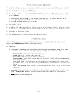
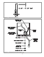
Refer to Part VII (Venting) to re-assemble any vent system components that are disassembled during this
inspection. Also refer to Part VII for details on supporting, pitching, and terminating the vent system.
s.
Replace any wiring
which has been disconnected.
t.
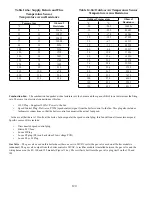
Inspect the hydronic system
. Look for leaks and repair any found. If system contains antifreeze, or other additives,
test and/or maintain them as directed by the additive manufacturer. See Part XI (Start-up and Checkout) for
important information on boiler water and the use of boiler water additives.
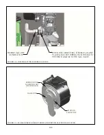
u.
[??
. To do this:
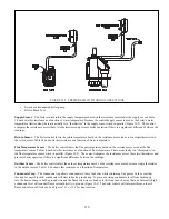
Q Start with the boiler in standby.
Q Either close a shut-off in the boiler loop or unplug the boiler pump at connector L1. (Figure 10.6)
Q #&## #' )^ & %##'' #
open.
v.
Follow ALL instructions in Part XI (Start-up and Checkout)
to place the boiler back in service, including the
performance of a combustion test.
"'!$
*()?C?(*@B*)?C??-!(
*))-(((A+)-
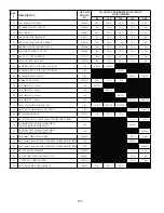
Summary of Contents for PHNTM080
Page 2: ......
Page 9: ...7 Figure 4 1 Minimum Clearances To Combustible Construction...
Page 11: ...9 Figure 5 1 Wall Layout Mounting Hole Location...
Page 12: ...10 Figure 5 2 Boiler Mounting Bracket Installation Boiler Wall Mounting...
Page 39: ...37 FIGURE 7 24 SPLIT VENT SYSTEM FLEX IN ABANDONED MASONRY CHIMNEY VENT OPTIONS 33 38...
Page 63: ...61 This page is intentionally left blank...
Page 68: ...66 FIGURE 9 2 PIPING METHOD 1 NEAR BOILER PIPING HEATING ONLY...
Page 72: ...70 FIGURE 9 6 PIPING METHOD 1 NEAR BOILER PIPING SHADED BOILER LOOP...
Page 82: ...80 FIGURE 10 4 PROPER INSTALLATION OF HEADER SENSOR...
Page 84: ...82 FIGURE 10 6 INTERNAL WIRING CONNECTIONS DIAGRAM...
Page 85: ...83...
Page 92: ...90 Lighting and Operating Instructions...
Page 101: ...99 FIGURE 12 5 SETTINGS MENU SEE PART C FOR ADDITIONAL INFORMATION...
Page 113: ...111 FIGURE 13 2 IGNITION ELECTRODE GAP FIGURE 13 3 CONDENSATE TRAP EXPLODED PARTS VIEW...
Page 125: ...123...
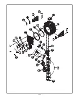
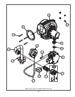
Page 127: ...125 40 33 31 27 28 34 35 37 38 32 39 36 29 30 48 Blower Gas Valve Assembly for 80 100 120...
Page 129: ...127...
Page 131: ...129...
Page 132: ...130...
Page 133: ...131...
Page 135: ...133...
Page 137: ...135 140 141 142 143 144 145...


