


1
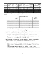
.%$&!"!$&."!$&""&'##=
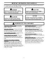
The following terms are used throughout this manual to bring attention to the presence of hazards of various risk levels,
or to important information concerning product life.
"&
))>((
?@A@?(@(
,((*BB)-
"'!$
B>((
?@A@)()
),(BB)-
"&
B>((
?@A@((@
(,((*BB)-
$!
B(@
B@)?)B
*(B,(>-
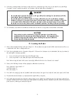
FOLLOW ALL INSTRUCTIONS and warnings
printed in this manual, the owner’s manual and
posted on the boiler.
MAINTAIN THE BOILER. To keep your boiler safe
and efficient, have a service technician maintain
this boiler as specified in Part XIII of the manual.
IF YOU ARE NOT QUALIFIED to install or service
boilers, do not install or service this one.
THE BOILER MAY LEAK WATER at the end of
its useful life. Be sure to protect walls, carpets,
and valuables from water that could leak from the
boiler.
PROTECT YOUR HOME IN FREEZING
WEATHER. A power outage, safety lockout, or
component failure will prevent your boiler from
lighting. In winter, your pipes may freeze and
cause extensive property damage. Do not leave
the heating system unattended during cold weather
unless alarms or other safeguards are in place to
prevent such damage
DO NOT BLOCK AIR FLOW into or around the
boiler. Insufficient air may cause the boiler to
produce carbon monoxide or start a fire.
KEEP FLAMMABLE LIQUIDS AWAY from the
boiler, including paint, solvents, and gasoline.
The boiler may ignite the vapors from the liquids
causing explosion or fire.
KEEP CHILDREN AND PETS away from hot
surfaces of the boiler, boiler piping, vent piping and
vent terminals.
CARBON MONOXIDE (CO) is an odorless, deadly
gas that may be introduced into your home by
any malfunctioning fuel-burning product or vent
system failure. Consider installing CO alarms near
bedrooms in all levels of the building to warn you
and your family of potential CO exposure.
WARNINGS FOR THE HOMEOWNER
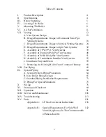
Summary of Contents for PHNTM080
Page 2: ......
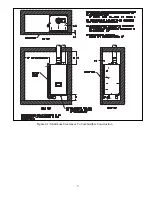
Page 9: ...7 Figure 4 1 Minimum Clearances To Combustible Construction...
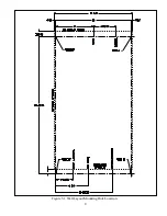
Page 11: ...9 Figure 5 1 Wall Layout Mounting Hole Location...
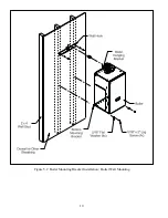
Page 12: ...10 Figure 5 2 Boiler Mounting Bracket Installation Boiler Wall Mounting...
Page 39: ...37 FIGURE 7 24 SPLIT VENT SYSTEM FLEX IN ABANDONED MASONRY CHIMNEY VENT OPTIONS 33 38...
Page 63: ...61 This page is intentionally left blank...
Page 68: ...66 FIGURE 9 2 PIPING METHOD 1 NEAR BOILER PIPING HEATING ONLY...
Page 72: ...70 FIGURE 9 6 PIPING METHOD 1 NEAR BOILER PIPING SHADED BOILER LOOP...
Page 82: ...80 FIGURE 10 4 PROPER INSTALLATION OF HEADER SENSOR...
Page 84: ...82 FIGURE 10 6 INTERNAL WIRING CONNECTIONS DIAGRAM...
Page 85: ...83...
Page 92: ...90 Lighting and Operating Instructions...
Page 101: ...99 FIGURE 12 5 SETTINGS MENU SEE PART C FOR ADDITIONAL INFORMATION...
Page 113: ...111 FIGURE 13 2 IGNITION ELECTRODE GAP FIGURE 13 3 CONDENSATE TRAP EXPLODED PARTS VIEW...
Page 125: ...123...
Page 127: ...125 40 33 31 27 28 34 35 37 38 32 39 36 29 30 48 Blower Gas Valve Assembly for 80 100 120...
Page 129: ...127...
Page 131: ...129...
Page 132: ...130...
Page 133: ...131...
Page 135: ...133...
Page 137: ...135 140 141 142 143 144 145...


