


35
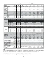
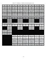
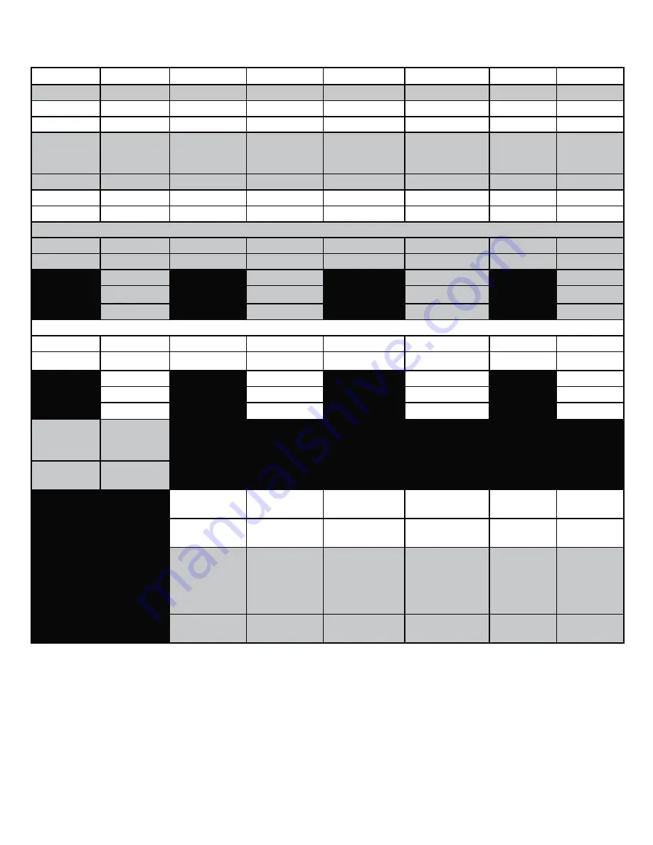
Table 7.21: Summary of Split Vent System Options (cont.)
31
32
33
34
35
36
37
38
7.22
7.22
7.23, 7.24
7.23, 7.24
7.23, 7.24
7.23, 7.24
7.23, 7.24
7.23, 7.24
Roof
Roof
Roof
Roof
Roof
Roof
Roof
Roof
Wall
Wall
Wall
Wall
Wall
Wall
Wall
Wall
Centrotherm
InnoFlue SW
Centrotherm
InnoFlue SW
DuraVent
PolyPro
(Rigid/Flex)
DuraVent
PolyPro
(Rigid/Flex)
(Rigid/Flex)
(Rigid/Flex)
Centrotherm
(Rigid/Flex)
Centrotherm
(Rigid/Flex)
PVC
PVC
PVC
PVC
PVC
PVC
PVC
PVC
2”
3”
2”
3”
2”
3”
2”
3”
2” or 3”
3”
2” or 3”
3”
2” or 3”
3”
2” or 3”
3”
Min Equivalent Vent Length:
48”
48”
48”
48”
48”
48”
48”
48”
48”
48”
48”
48”
48”
48”
48”
48”
48”
48”
48”
48”
52”
52”
52”
52”
52”
52”
52”
52”
Max Equivalent Vent Length (Note 1):
60ft
135ft
60ft
135ft
60ft
135ft
60ft
135ft
60ft
135ft
60ft
135ft
60ft
135ft
60ft
135ft
135ft
135ft
135ft
135ft
135ft
135ft
135ft
135ft
135ft
135ft
135ft
135ft
ISEP02 or
ISEP0239 w
Screen
ISEP03 or
ISEP0339 w
Screen
90 Elbow w
Screen
90 Elbow w
Screen
2PPS-FK
2PPS-FLEX**
3PPS-FK
3PPS-FLEX**
2PF-FLEX-KIT
2PF-FLEX
3PF-FLEX-KIT
3PF-FLEX
IFCK02**
IFCK03**
90 Elbow w
Screen
90 Elbow w
Screen
90 Elbow w
Screen
90 Elbow w
Screen
90 Elbow w
Screen
90 Elbow w
Screen
2PPS-VFT
2PPS-BF*
2PPS-FLEX**
3PPS-VFT
3PPS-BF*
3PPS-FLEX**
2PF-10UV or
2PF-39UV w
Screen
2PF-BVSC
(Note 4)
3PF-10UV or
3PF-39UV w
Screen
3PF-BVSC
(Note 4)
IFBK02****
IFBK03****
90 Elbow w
Screen
90 Elbow w
Screen
90 Elbow w
Screen
90 Elbow w
Screen
90 Elbow w
Screen
90 Elbow w
Screen
Summary of Contents for PHNTM080
Page 2: ......
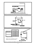
Page 9: ...7 Figure 4 1 Minimum Clearances To Combustible Construction...
Page 11: ...9 Figure 5 1 Wall Layout Mounting Hole Location...
Page 12: ...10 Figure 5 2 Boiler Mounting Bracket Installation Boiler Wall Mounting...
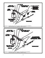
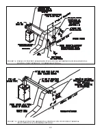
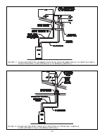
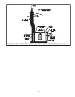
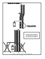
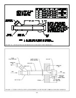
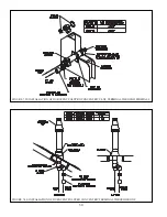
Page 39: ...37 FIGURE 7 24 SPLIT VENT SYSTEM FLEX IN ABANDONED MASONRY CHIMNEY VENT OPTIONS 33 38...
Page 63: ...61 This page is intentionally left blank...
Page 68: ...66 FIGURE 9 2 PIPING METHOD 1 NEAR BOILER PIPING HEATING ONLY...
Page 72: ...70 FIGURE 9 6 PIPING METHOD 1 NEAR BOILER PIPING SHADED BOILER LOOP...
Page 82: ...80 FIGURE 10 4 PROPER INSTALLATION OF HEADER SENSOR...
Page 84: ...82 FIGURE 10 6 INTERNAL WIRING CONNECTIONS DIAGRAM...
Page 85: ...83...
Page 92: ...90 Lighting and Operating Instructions...
Page 101: ...99 FIGURE 12 5 SETTINGS MENU SEE PART C FOR ADDITIONAL INFORMATION...
Page 113: ...111 FIGURE 13 2 IGNITION ELECTRODE GAP FIGURE 13 3 CONDENSATE TRAP EXPLODED PARTS VIEW...
Page 125: ...123...
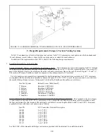
Page 127: ...125 40 33 31 27 28 34 35 37 38 32 39 36 29 30 48 Blower Gas Valve Assembly for 80 100 120...
Page 129: ...127...
Page 131: ...129...
Page 132: ...130...
Page 133: ...131...
Page 135: ...133...
Page 137: ...135 140 141 142 143 144 145...


