


45
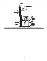
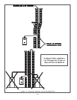
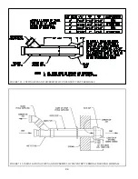
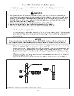
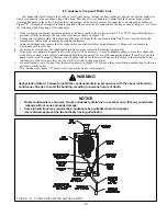
FIGURE 7.34: INSTALLATION OF IPEX AND DIVERSITECH CONCENTRIC TERMINAL THROUGH ROOF
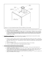
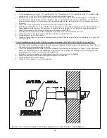
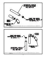
e. Cement the outer pipe to the Wye, being careful, to keep the inner and outer pipes concentric.
f.
Slip the partially assembled terminal through the wall or ceiling from the inside and for horizontal installations
orient so that the side outlet on the Wye is on or above the horizontal plane.
g. For horizontal installations, seal the gap between the OD of the “outer pipe” and the exterior side of the wall with
RTV sealant.
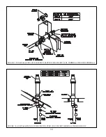
h. Cement the rain cap onto the inner pipe. If desired, the rain cap can be attached to the inner pipe with the supplied
stainless steel screw and nut so that it can be later removed for cleaning and inspection. If this is done, drill a
3/16”clearance hole in the rain cap and inner pipe in the location shown on Figure 7.32 for the size terminal kit
%&&*'&) %#& && &#&
of the rain cap.
i. ^) \# %&) %# & %
## %# %%& ## #
collar after verifying that the bottom of the rain cap will be at least 12” above the normal snow line. Apply RTV to
seal the storm collars to the terminal.
Summary of Contents for PHNTM080
Page 2: ......
Page 9: ...7 Figure 4 1 Minimum Clearances To Combustible Construction...
Page 11: ...9 Figure 5 1 Wall Layout Mounting Hole Location...
Page 12: ...10 Figure 5 2 Boiler Mounting Bracket Installation Boiler Wall Mounting...
Page 39: ...37 FIGURE 7 24 SPLIT VENT SYSTEM FLEX IN ABANDONED MASONRY CHIMNEY VENT OPTIONS 33 38...
Page 63: ...61 This page is intentionally left blank...
Page 68: ...66 FIGURE 9 2 PIPING METHOD 1 NEAR BOILER PIPING HEATING ONLY...
Page 72: ...70 FIGURE 9 6 PIPING METHOD 1 NEAR BOILER PIPING SHADED BOILER LOOP...
Page 82: ...80 FIGURE 10 4 PROPER INSTALLATION OF HEADER SENSOR...
Page 84: ...82 FIGURE 10 6 INTERNAL WIRING CONNECTIONS DIAGRAM...
Page 85: ...83...
Page 92: ...90 Lighting and Operating Instructions...
Page 101: ...99 FIGURE 12 5 SETTINGS MENU SEE PART C FOR ADDITIONAL INFORMATION...
Page 113: ...111 FIGURE 13 2 IGNITION ELECTRODE GAP FIGURE 13 3 CONDENSATE TRAP EXPLODED PARTS VIEW...
Page 125: ...123...
Page 127: ...125 40 33 31 27 28 34 35 37 38 32 39 36 29 30 48 Blower Gas Valve Assembly for 80 100 120...
Page 129: ...127...
Page 131: ...129...
Page 132: ...130...
Page 133: ...131...
Page 135: ...133...
Page 137: ...135 140 141 142 143 144 145...


