background image

Commercial Audio Series

 Mixer-Amplifiers

page 7

Operation Manual

1 Welcome

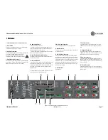
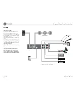
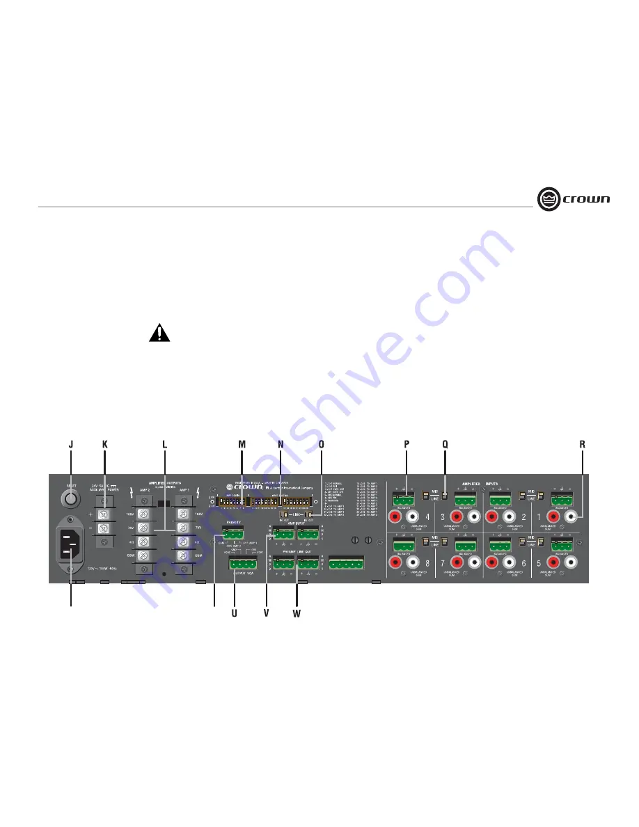
Figure 1.2  Back Panel Controls and Connectors
                             (280MA shown)

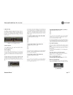
M. Amp Config Switch

A DIP switch with two functions:
1. Assigns one of the inputs as the priority input for each 
output, thereby temporarily muting the remaining inputs. 
Muting is activated by contact closure.
 2. Global enable switch for phantom power. Does not affect 
RCA inputs. Default position is off. 

N. Input Routing Switch (280MA only)

DIP switches that assign each input signal to each output. 
Two switches per input. 

O. Link In/Out Switch


Slide switch, one per channel. With the Link Switch IN, any 
signal applied to the Amp Input connector will be mixed 
with the input signal(s). With the Link Switch OUT, only the 
signal from the Amp Input Connector will appear at the 
amplifier output.

The tone generator has been omitted. Call Crown Tech Sup-
port if you have a tone generator question.

P. Mic/Line Input Connector

3-pin Phoenix-type, balanced, one per input channel.

Q. Mic/line Switch

Selects mic-level or line-level input signals. One switch for 
each balanced input.

R. Dual RCA Input Connector

For stereo music signals, unbalanced, summed together, 
two connectors per input channel. If required, both the mic/
line and RCA inputs may be used at the same time. The mic/
line gain switch does not affect the RCA gain, which is fixed 
relative to mic/line. The mic/line and RCA signals are 
mixed. Note: Other equipment connected to the RCA jacks 
should be connected to the same AC power source as the 
mixer-amp to avoid hum.

S. AC Power Inlet

Detachable IEC.

T. Priority Connector

3-pin Phoenix-type connector allows Input 1 or Input 5 
(280MA only) to mute other input signals by contact clo-
sure.

U. Output VCA Connector

4-pin Phoenix-type connector for one (180MA) or two 
(280MA) VCA control lines of +10 VDC and ground. Com-
patible with Crown 1-VCAP and 4-VCAP modules.

V. Amp Input Connector

3-pin Phoenix-type, high-impedance balanced, one per 
amplifier channel. Used to link an additional mixer to the 
mixer-amplifier. Or used to connect an external processor 
(see Section 2.9).

W. Line Out Connector

One 3-pin balanced Phoenix-type connector per output 
channel. Post master, pre-VCA. Level controlled by master 
volume control.

1.3 Back Panel Controls and Connectors

J. Reset Switch

Resets the circuit breaker that protects the power supply. 
220/230/240V units have a fuse instead.

K. Auxiliary Power Input

2-position terminal strip for 24 VDC (±10%) backup power. 
Accepts up to 10 AWG terminal forks. NOTE: To 
prevent a spark when attaching a battery, have 
unit turned on and connected to the mains supply.

L. Amplifier Outputs Connectors

One per channel, 4-position terminal strip with COM (Com-
mon), 4 ohms, 70V and 100V terminals. Accepts up to 14 
AWG terminal forks. Non-touch cover included

.

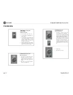
NO FUNCTION 


T

Summary of Contents for 1160MA

Page 1: ...nstallation operation or maintenance The information provided in this manual was deemed accurate as of the publication date However updates to this information may have occurred To obtain the latest version of this manual please visit the Crown website at www crownaudio com Trademark Notice Crown Crown Audio and Amcron are registered trademarks of Crown International Other trademarks are the prope...

Page 2: ...ided plug does not fit into your outlet consult an electrician for replacement of the obsolete outlet 10 Protect the power cord from being walked on or pinched particularly at plugs convenience receptacles and the point where they exit from the apparatus 11 Only use attachments accessories specified by the manufacturer 12 Use only with a cart stand tripod bracket or table specified by the manufact...

Page 3: ...paratus for Professional Use Part 2 Immunity EN 61000 4 2 2001 Electrostatic Discharge Immunity Environment E2 Criteria B 4k V Contact 8k V Air Discharge EN 61000 4 3 2001 Radiated Radio Frequency Electromagnetic Immunity Environment E2 Criteria A EN 61000 4 4 2001 Electrical Fast Transient Burst Immunity Criteria B EN 61000 4 5 2001 Surge Immunity Criteria B EN 61000 4 6 2003 Immunity to Conducte...

Page 4: ...Phantom Power 11 2 8 Priority Muting 11 2 9 Link In Out Switches 11 2 10 Remote Volume Control 12 2 11 Powering Up 12 2 12 Included Accessories 12 2 13 Optional Accessories 12 2 14 Block Diagram 13 3 Troubleshooting 14 4 Specifications 15 5 Service 16 5 1 Worldwide Service 16 5 2 US and Canada Service 16 5 2 1 Service at a US or Canada Service Center 16 5 2 2 Factory Service 16 5 2 3 Factory Servi...

Page 5: ...ch proofed screw terminal speaker outputs Independent Bass and Treble controls on each input Any input can be sent to any output Priority muting Advanced protection system includes output current limiting DC protection circuit breaker fuse and thermal protection Details available online at www crownaudio com Three Year No Fault Fully Transferable Warranty completely protects your investment and gu...

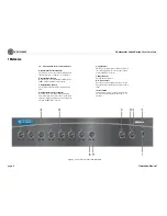
Page 6: ...th knob D Output Signal Presence Indicator Green LED one for each output channel illuminates when output signal level exceeds 100 mV 45 dB below full power from the 4 ohm tap Does not respond to sig nals from the AMP INPUT connector E Clip Indicator Red LED one per output channel illuminates at thresh old of audible distortion Does not respond to signals from the AMP INPUT connector F Power Indica...

Page 7: ...ain switch does not affect the RCA gain which is fixed relative to mic line The mic line and RCA signals are mixed Note Other equipment connected to the RCA jacks should be connected to the same AC power source as the mixer amp to avoid hum S AC Power Inlet Detachable IEC T Priority Connector 3 pin Phoenix type connector allows Input 1 or Input 5 280MA only to mute other input signals by contact c...

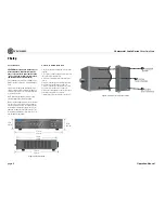
Page 8: ...tly on top of each other Allow 2 U between units for convection cooling The side walls of the rack should be a minimum of two inches 5 1 cm away from the amplifier sides and the back of the rack should be a minimum of four inches 10 2 cm from the amplifier back panel Figure 2 1 Dimensions 17 3 In 43 8 cm 13 9 In 35 2 cm 4 1 In 10 5 cm 3 5 In 8 9 cm 12 2 In 31 0 cm 2 2 How to Attach Rack Ears 1 Loc...

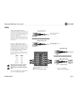
Page 9: ...You may use crimp on spade lugs for your output connectors Figure 2 5 To prevent the possibility of short circuits wrap or otherwise insulate exposed loudspeaker cable connectors Cover the output con nections with the supplied non touch cover Using the guidelines below select the appropriate size of wire based on the distance from amplifier to speaker The wire sizes apply to the 4 ohm tap Distance...

Page 10: ...dspeaker loads Use terminals marked COM and 4 OHMS for a 4 ohm loudspeaker load or use terminals marked COM and 70V or 100V for con stant voltage loudspeaker loads Connect the COM terminal to speaker negative lead connect one of the other terminals to speaker positive lead For more application drawings see the enclosed Commercial Audio Mixer Amplifier Quick Start Guide NOTE Crown provides a refere...

Page 11: ... the priority input for each amplifier output which tem porarily mutes the remaining inputs Muting is activated by contact clo sures For example suppose you configured Channel 1 as the priority input Mic 1 is plugged into Channel 1 A press to talk switch in Mic 1 is wired to the Priority connector in the mixer amplifier When you press the mic switch all other signals are muted so you can make an a...

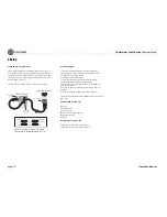
Page 12: ... wiring or installation changes disconnect the power cord 2 12 Included Accessories Power cord Detachable rack ears Screws for rack ears Non touch cover for output connectors Phoenix type connectors Spade lugs 2 13 Optional Accessories 1 VCAP remote volume control for one channel 4 VCAP remote volume control for four channels Figure 2 11 Wiring a 1 VCAP or 4 VCAP Level Control to the Output VCA Co...

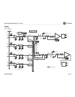
Page 13: ...Bal Input Gain Ch 5 Priority SW6 CH 5 Tone Control Bass Trebl e Gain 5 SPI Input Gain Mic Line Bal RCA Line Mi c Ch 5 Normal SW5 Ch 5 to Amp 1 SW17 Ch 5 to Amp 2 SW18 CH 6 Tone Control Bass Trebl e Gain 6 SPI RCA Line Mi c Ch 6 to Amp 1 SW19 Ch 6 to Amp 2 SW20 Mic Line Bal Input Gain Ch 3 and Ch 4 similar to Ch 2 Ch 7 and Ch 8 similar to Ch 6 Out In Amp Input 1 Limiter VCA 1 Ch 1 Amp 1 Mute Ch 5 A...

Page 14: ... volume controls NOTE Your mixer amplifier should never be operated at a level which causes the Clip LEDS to illuminate con stantly Master volume level is too high Turn it down to about 3 4 of maximum level CONDITION No sound POSSIBLE REASON The amplifier is in fault mode A Fault status can be triggered when one of the amplifier s protection circuits is activated First disconnect your speakers fro...

Page 15: ...0 ohms Line 100 kilohms RCA 50 kilohms Mic 400 ohms Line 100 kilohms RCA 50 kilohms Mic 400 ohms Line 100 kilohms RCA 50 kilohms Crosstalk all controls at 10 70 dB at 1 kHz 70 dB at 1 kHz 70 dB at 1 kHz Line Output Level nominal 1V into 10 kilohms 1V into 10 kilohms 1V into 10 kilohms Phantom Power 15 VDC 15 VDC 15 VDC AC Line Voltages Available 100V 50 60 Hz 120V 60 Hz 220V 50 60 Hz 230V 50 60 Hz...

Page 16: ... Or if you prefer you may prepay the cost of shipping and Crown will reimburse you Send copies of the shipping receipts to Crown to receive reimbursement Your repaired unit will be returned via UPS ground Please contact us if other arrangements are required 5 2 3 Factory Service Shipping Instruc tions 1 Service Return Authorization SRA is required for product being sent to the factory for service ...

Page 17: ...he defec tive product at our authorized service center or our factory All expenses in remedying the defect including surface shipping costs in the United States will be borne by us You must bear the expense of shipping the product between any for eign country and the port of entry in the United States including the return shipment and all taxes duties and other customs fees for such for eign shipm...

Page 18: ...al purchase price not including inter est insurance closing costs and other finance charges less a reasonable depreciation on the product from the date of original purchase War ranty work can only be performed at our autho rized service centers We will remedy the defect and ship the product from the service center within a reasonable time after receipt of the defec tive product at our authorized s...

Page 19: ...ntry __________________________ E mail address ___________________________________________ Phone include area code ___________________________ Fax __________________________________ MODEL SERIAL PURCHASE DATE e g IT8000 CDi1000 PCC160 e g 8000000000 mo day yr ________________________________ ____________________ ______ _____ _____ ________________________________ ____________________ ______ _____ ...

Page 20: ...Commercial Audio Series Mixer Amplifiers page 20 Operation Manual THIS PAGE INTENTIONALLY LEFT BLANK ...

Page 21: ..._________________________________________________________________________________________________________________________________________________ Other equipment in your system ___________________________________________________________________________________________________________________________________________________________________________ If warranty is expired pleae provide method of paym...

Page 22: ...Commercial Audio Series Mixer Amplifiers page 22 Operation Manual THIS PAGE INTENTIONALLY LEFT BLANK ...

Page 23: ...Commercial Audio Series Mixer Amplifiers page 23 Operation Manual THIS PAGE INTENTIONALLY LEFT BLANK ...

Page 24: ......

Reviews: