Page 18
Contractor Series Power Amplifiers
Reference Manual
4 Operation
4.1 Precautions
Contractor Series amplifiers are protected from internal
and external faults, but you should still take the follow-
ing precautions for optimum performance and safety:
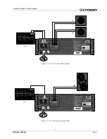
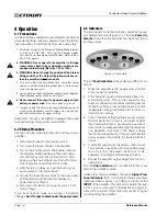
1. Improper wiring for the Stereo or Bridge-Mono modes,
as well as the 4/8 Ohm, 70V and 100V output modes
can result in serious operating difficulties. Refer to Sec-
tion 9.4 for details.
2. WARNING: Never operate the amplifier in Bridge
mode unless both Output Operation switches are
configured identically (4/8 Ohm, 70V or 100V).
3. WARNING: Do not change the position of the Stereo/
Bridge switch or the Output Operation switches un-
less the amplifier is first turned off.
4. Use care when making connections, selecting signal
sources and controlling the output level. The load you
save may be your own!
5. Do not connect input and output ground leads together.
Ground loops and oscillations may result.
6. Never connect the output to a power supply output,
battery or power main.
Electrical shock may result.
7. Tampering with the circuitry by unqualified personnel, or
making unauthorized circuit changes may be hazard-
ous and invalidates all agency listings.
Remember: Crown is not liable for damage that results
from overdriving other system components.
4.2 Startup Procedure
Use the following procedure when first turning on your
amplifier:
1. Turn down the level of your audio source.
2. Turn down the level controls of the amplifier.
3. Turn on the Enable switch. The Enable indicator
should glow. During power-up, the Fault indica-
tors will flash as described in Section 4.3. After
power-up, the Fault indicators will turn off and all
other indicators should function normally.
4. After the turn-on delay, turn up the level of your
audio source to the desired level.
5. Turn up the Input Level controls on the back panel
of the amplifier until the desired loudness or
power level is achieved.
6. Turn down the level of your audio source to its
normal range.
If you ever need to make any wiring or installation
changes,
don’t forget to disconnect the power cord.
4.3 Indicators
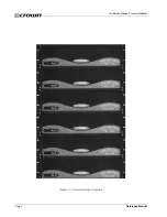
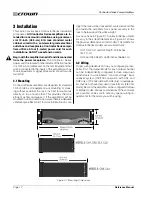
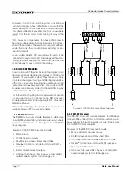
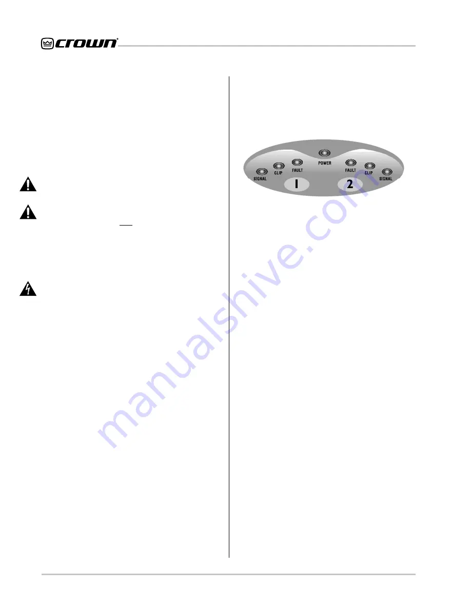
The front panel of a Contractor Series amplifier has sev-
eral helpful indicators (Figure 4.1). The blue
Power in-
dicator
shows that the amplifier has been turned on
and has power.
Figure 4.1 Indicators
The red
Fault indicators
blink under five different con-
ditions:
1.
When the amplifier is first powered up, until the
unit is ready for operation.
2.
If the heatsinks reach a temperature above nor-
mal working limits. This can be caused by any
number of abnormal conditions including but not
limited to extremely low load impedance and/or
inadequate cooling (see Section 9.1 for more in-
formation on cooling).
3.
If the transformer (high-voltage power supply)
thermal protection circuit is activated. Higher
than rated output levels, excessively low-imped-
ance loads and unreasonably high input signals
can generate more heat in the power supply
than in the output devices. This can overheat the
power supply and activate the Fault protection
circuit.
4.
If amplifier output wires develop a short-circuit.
This could be caused by a short anywhere along
the circuit from the output connectors to the
speakers, including shorted speaker drivers.
5.
Should the amplifier output stage become non-
operational.
The red
Clip indicators
turn on when distortion is au-
dible in the amplifier output.
Unlike other Crown amplifiers, the green
Signal Pres-
ence Indicators
(SPI) on Contractor Series amplifiers
illuminate when a signal (>–40 dBm) is present at the
INPUT
of the amplifier. This indicator is before the level
control, so it can be used to troubleshoot wiring prob-
lems within a system. If the indicators are not lit, signal
is not reaching the amplifier.


