Page 19
Contractor Series Power Amplifiers
Reference Manual
4.4 Controls
The
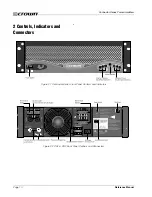
Enable switch
is located on the front panel so you
can easily turn the amplifier on and off.
A 21-position
Precision Detented Level Control
is pro-
vided for each channel. Level attenuation may be ad-
justed in precise steps. For security, the level controls
are located on the back panel.
Input Sensitivity
is fac-
tory set for 1.4V for each channel. With this setting, a
1.4V input signal will drive the amplifier to full power into
an 8-ohm load when the Level Controls are turned to
maximum. This setting works best when the amplifier is
being driven by equipment with a +4 dBu output. Op-
tionally, the Input Sensitivity for each channel may be
individually set to either 0.775V or 26 dB. To have the
input sensitivity changed on your amplifier, contact a
Crown authorized servicer (see Section 11) .
A two-position
Mode switch
, located on the back panel,
allows the selection of either Stereo or Bridge mode of
operation.
Stereo mode provides identical power output to each of
the two amplifier output channels. Bridge mode com-
bines the two amplifier output channels into a single
mono channel with twice the voltage of a single stereo
channel. It does this by bridging the outputs, and it re-
quires special output wiring.
Do NOT select Bridge
mode without first making sure the amplifier has
been wired in a Bridge-Mono configuration.
For more
information on wiring for Bridge mode, see the Installa-
tion section of this manual (Section 3)
, or consult your
system installer.
When Bridge mode is selected, only the Channel 1
Level control and the Channel 1 Signal indicator will
work. If the Channel 2 input is wired, the Channel 2 Level
Control should be turned all the way down
(counter/anti-
clockwise) to prevent distortion.
A two-position
Output Operation switch
(CH Series
amplifiers only) allows the selection of either 4/8 ohm,
70V or 100V output from the amplifier. See Section 9 for
more information about output operating modes.
Fault Jack:
This RJ11 jack (which looks like a phone
jack) is located on the back panel. By attaching a signal-
ling device to the Fault jack, you can monitor the amplifier’s
Fault status from a remote location. See the Advanced
Features and Options section (Section 5) of this manual
for more information on fault monitoring and suggestions
for signalling device circuity.
A circuit breaker is provided to prevent the high-voltage
power supplies from drawing excessive current. A
Re-
set switch
for the circuit breaker is provided on the back
panel. If the circuit breaker trips, the Power indicator
turns off. In this situation, turn off the Power switch and
reset the circuit breaker. Then, turn the Power switch
back on. If it trips again or the unit fails to operate prop-
erly, contact an authorized service center or Crown’s
Technical Support Group.
5 Advanced Features and
Options
5.1
BCA
®
(CH4 and CL4 Only)
BCA (Balanced Current Amplifier) is Crown’s patented,
cutting-edge technology that gets more power out of an
amplifier with less waste than was ever before possible.
A completely new adaptation of standard amplifier de-
sign, Crown’s BCA “switching” amplifier design pro-
vides for high output, exceptional reliability and nearly
twice the efficiency of typical amplifier designs.
While switching designs have been used successfully
in other applications, these designs were never before
suitable for use in precision, high-power audio amplifier
applications. Crown’s BCA technology changes that,
with a totally new paradigm for amplifier design that rep-
resents the future of professional amplifiers.
With their superior efficiency, BCA amplifiers can help
to keep power requirements lower, while still providing
excellent audio reproduction. And Crown BCA amplifi-
ers are tough—easily handling very low (and highly re-
active) load impedances, even under extreme
conditions. In fact, Crown BCA amps have far out-per-
formed competitive amplifiers in tests where the ampli-
fier was run as much as 12-dB into clip for extended
periods of time.
5.2 Switching Power Supply with PFC (CH4 and
CL4 Only)
Crown’s new Switching Power Supply with PFC pro-
vides a range of benefits over both non-switching and
conventional switching power-supply designs.
Typical non-switching power supplies require large
transformers in order to produce the required power at
the output stage. These transformers must be large to
absorb the waste that occurs when operating at 50 to
60 Hz (standard AC supplied by the power company).
By contrast, switching power supplies can operate with
a much smaller (and lighter) transformer because they
first convert the AC up to a much higher frequency,
thereby reducing waste.


