Page 39
Contractor Series Power Amplifiers
Reference Manual
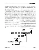
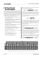
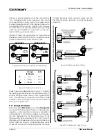
Figure 9.10 Inductive Load (Transformer) Network
4 ohm, 20 watt
Resistor
590 to 708
µ
f Capacitor
120 VAC, N.P.
+
–
Inductive
Load
+
–
From
Amplifier
Output
line. Note: Wire size increases as the AWG gets smaller.
7. If the size of the cable exceeds what you want to use,
(1) find a way to use shorter cables, (2) settle for a lower
damping factor, or (3) use more than one cable for each
line. Options 1 and 2 will require the substitution of new val-
ues for cable length or damping factor in the nomograph.
For option 3, estimate the effective wire gauge by subtract-
ing 3 from the apparent wire gauge every time the number
of conductors of equal gauge is doubled. So, if #10 wire is
too large, two #13 wires can be substituted, or four #16
wires can be used for the same effect.
9.4.1 Solving Output Problems
High-frequency oscillations
can cause your amplifier
to prematurely activate its protection circuitry. The ef-
fects of this problem are similar to the RF problems de-
scribed in Section 9.2.1. To prevent high-frequency
oscillations:
1. Bundle together each pair of loudspeaker conductors
when using long cable runs or when different amplifiers
use a common cable tray or jacket. (Do NOT bundle
wires from different amplifiers.) This reduces the
chance of conductors acting like antennas to transmit
or receive the high frequencies that can cause oscilla-
tion.
2. Avoid using shielded loudspeaker cable.
3. Never tie together input and output grounds.
4. Never tie together the output of different amplifiers.
5. Keep output cables separated from input cables.
6. Install a low-pass filter in series with each input (see
Section 9.3.1).
7. Install the input wiring according to the instructions in
Section 9.2.
Another problem to avoid is the presence of large
infra-
sonic (sub-audible) currents
when primarily inductive
loads are used. Examples of inductive loads are 70-volt
transformers and electrostatic loudspeakers.
Inductive loads can appear as a short circuit at low fre-
quencies. This can cause the amplifier to produce large
low-frequency currents and activate its protection cir-
cuitry. CH Series amplifier have a third-order (18-dB-
per-octave) 70-Hz high-pass filter that is which is
automatically inserted into the signal path at the input
when in 70V or 100V mode. If driving an inductive load,
either with a CH Series amplifier in 4/8 ohm mode or
with a CL Series amplifier, always take the precaution of
installing a high-pass filter in series with the amplifier’s
input. An 18-dB-per-octave filter between 50 and 70 Hz
is recommended.
Another way to protect inductive loads from large low-
frequency currents and prevent the amplifier from pre-
maturely activating its protective systems is to parallel a
590 to 708 µF nonpolarized motor start capacitor and a
4-ohm, 20-watt resistor in series with the amplifier out-
put and the positive (+) transformer lead. This circuit is
shown in Figure 8.10. It uses components that are avail-
able from most electrical supply stores.
9.4.2 Additional Load Protection
Contractor Series amplifiers can generate enormous
power output. Using 4/8 ohm output, if your loudspeak-
ers do not have built-in protection from excessive power,
it’s a good idea to protect them. Loudspeakers are sub-
ject to thermal damage from sustained overpowering
and mechanical damage from large transient voltages.
In both cases, special fuses may be used to protect
your loudspeakers, or you may opt to use an outboard
limiter to provide loudspeaker protection.
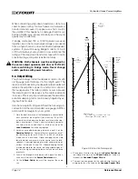
Two different types of fuses are required for thermal pro-
tection and voltage protection. Slow-blow fuses are usu-
ally selected to protect loudspeakers from thermal
damage because they are similar to loudspeakers in
the way they respond to thermal conditions over time.
In contrast, high-speed instrument fuses like the
Littelfuse 361100 series are used to protect loudspeak-
ers from large transient voltages. The nomograph in Fig-
ure 9.11 can be used to select the properly rated fuse
for either type of loudspeaker protection.
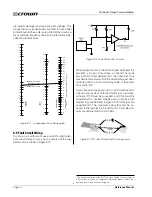
There are mainly two different approaches used when
installing fuses for loudspeaker protection. A common
practice is to put a single fuse in series with the output
of each channel. This makes installation easy because
there is only one fuse per channel to install, but it can
also lead to problems. The biggest disadvantage be-
comes apparent if the fuse blows because power to all
connected loads will be removed.
A better approach is to fuse each driver independently.
This allows you to apply the most appropriate protec-
tion for the type of driver being used. In general, low-
frequency drivers (woofers) are most susceptible to
thermal damage and high-frequency drivers (tweeters)

