Page 6
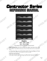
Contractor Series Power Amplifiers
Reference Manual
CONTENTS
1 Welcome ................................................................................ 9
1.1 Unpacking ............................................................................ 9
1.2 Features ................................................................................ 9
2 Controls, Indicators and Connectors ................................... 10
3 Installation ............................................................................ 12
3.1 Mounting ............................................................................. 12
3.2 Wiring
.............................................................................. 12
3.2.1 Input Wiring .............................................................. 13
3.2.2 Output Wiring ........................................................... 13
4 Operation .............................................................................. 18
4.1 Precautions ......................................................................... 18
4.2 Startup Procedure ............................................................... 18
4.3 Indicators ............................................................................ 18
4.4 Controls .............................................................................. 19
5 Advanced Features and Options ......................................... 19
5.1 BCA
®
(CH4 and CL4 Only) .................................................. 19
5.2 Switching Power Supply with PFC (CH4 and CL4 Only) ....... 19
5.3 Crown SST Modules ............................................................ 20
5.3.1 SST-MX Crossover .................................................... 20
5.3.2 SST-SX Crossover ..................................................... 20
5.3.3 SST-SBSC Module .................................................... 21
5.4 Fault Monitoring ................................................................... 21
5.5 Constant Voltage Computer ................................................. 21
6 Principles of Operation ........................................................ 22
6.1 CH1, CH2, CL1 and CL2 ..................................................... 22
6.2 CH4 and CL4 ...................................................................... 24
6.2.1 Audio Signal Path ..................................................... 24
6.2.2 Power Supply Operation ........................................... 26
7 Specifications ....................................................................... 27
8 AC Power Draw and Thermal Dissipation ............................ 32
9 Installation Helps .................................................................. 35
9.1 Cooling .............................................................................. 35
9.1.1 Additional Cooling .................................................... 35
9.2 Input Wiring ......................................................................... 35
9.2.1 Solving Input Problems ............................................. 36
9.3 More About Output Modes .................................................. 37
9.3.1 4/8 ohm Operation (CH and CL Series) ..................... 37
9.3.2 70V and 100V Operation (CH Series Only) ................ 37
9.4. Output Wiring ..................................................................... 38
9.4.1 Solving Output Problems .......................................... 39
9.4.2 Additional Load Protection ........................................ 39
9.5 Fault Circuit Wiring .............................................................. 40
10 Applications ........................................................................ 41
10.1 Restaurant ......................................................................... 41
10.2 House of Worship .............................................................. 42
11 Service .............................................................................. 43

