INSTALLATION AND OPERATION MANUAL, DIRECT STEAM SINGLE & TWIN MIXER
KETTLE, MODELS DLTM-40 TO DLTM-100 AND DLTM-40-2 TO DLTM-100-2
4.0 INSTALLATION INSTRUCTIONS
The kettle must be installed in accordance with State and/or local codes. In the USA, the
National Electrical code, ANSI/NFPA-70 (latest edition). In Canada, the Canadian Electrical
Code, Part 1, CSA Standard C22.1 (latest edition).
1.
Select a location to provide drainage for kettle pour path when tilted and for butterfly valve
if so equipped. Allow sufficient rear clearance from wall for access to rear service panel on
hydraulic console.
2.
Level unit. Mark anchoring hole locations through flanged adjustable feet.
3.
Remove unit and drill holes as marked and, insert expansion shields to accommodate
5/16" size lag bolts.
4.
Reposition unit. Re-check level.
5.
Bolt down unit and seal bolts with Silastic or equivalent sealing compound. Sealant must
be applied not only to bolt heads but also around flanges making contact with the floor
surface to fulfil NSF requirements. Wipe off excess sealant immediately.
6.
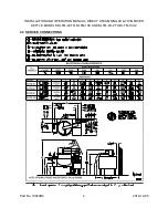
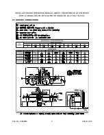
Connect steam line (3/4" pipe size) to the steam inlet. Make sure there is a steam control
valve strainer convenient to the unit. If incoming steam pressure is greater than kettle
maximum operating pressure, then a pressure reducing valve must be installed in the line.
If large amounts of water accumulate in the steam line it will be necessary to install one or
more ball float traps in the line to eliminate the water. A steam line pressure gauge is also
recommended to determine the actual amount of steam coming to the kettle.
7.
Connect the condensate return line to a drain or to the boiler return line. Return line must
have a check valve.
8.
Connect cold water supply line as indicated in bottom of hydraulic console.
9.
A control box with a power supply equivalent to the electrical rating of the unit should be
located nearby. A waterproof electrical connection for the power supply to the unit must be
provided.
10. Connect power supply as indicated.
11. Relief valves on the kettles must not be adjusted or closed off as they are set to relieve
excess pressure in the kettles.
12. Do not make any adjustments to the hydraulic valves as they have all been adjusted at the
factory.
13. Turn unit on when electrically connected, and check for proper operation.
Part No. 10040R4
7
2018-12-05

