INSTALLATION & OPERATION MANUAL 10100 REV 0 (04/21)
PAGE
4
OF 16
G
as
P
ower
T
ilt
S
killets
S
ERVICE
C
ONNECTIONS
S
ERVICE
C
ONNECTIONS
GAS CHARACTERISTICS
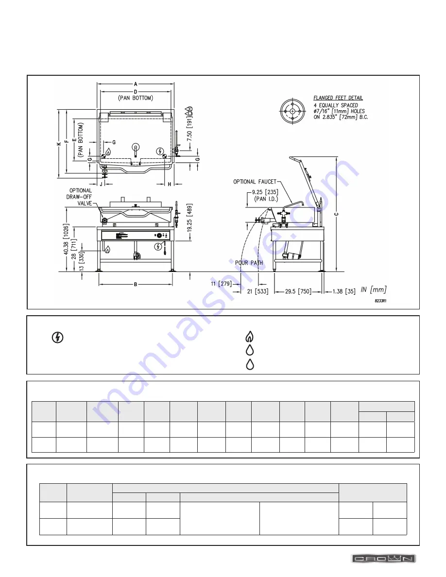
DIMENSIONS
* For use on non-combustible floors only.
SERVICE CONNECTIONS
- Unless otherwise specified, Field Wire Electrical Connection to
be 120 Volts, 60 Hz, single phase with grounding wire. Unit
furnished with 6’ cord and 3 prong plug. Total max amps 4.0.
C
H
Model
Capacity
Units
A
B
C
D
E
F
G
H
J
K
Ø2
Ø3
GLTS-30 30 Gallons
(114 liters)
inches
(millimeters)
36”
(914 mm)
33.88”
(860 mm)
72.25”
(1835 mm)
33.5”
(851 mm)
23.5”
(597 mm)
39.50”
(1003 mm)
4”
(102 mm)
6”
(152 mm)
3.75”
(95 mm)
42.88”
(1089 mm)
48.5”
(1232 mm)
GLTS-40 40 Gallons
(152 liters)
inches
(millimeters)
48”
(1219 mm)
45.88”
(1165 mm)
71.75”
(1822 mm)
43.5”
(1105 mm)
23”
(584 mm)
39.88”
(1013 mm)
4”
(102 mm)
6”
(152 mm)
4.75”
(121 mm)
42.88”
(1089 mm)
48.5”
(1232 mm)
Model
Shipping
Weight
Gas Supply
Minimum Clearance *
BTU/HR
kW/HR
Supply Pipe Pressure (W.C)
GLTS-30
550 lbs.
[249 kg]
80,000
23.4
Natural
6” - 14”
(152 mm - 356 mm)
Propane
11” - 14”
(279 mm - 356 mm)
Sides
3”
(76 mm)
GLTS-40
736 lbs.
[334 kg]
100,000
29.3
Back
6”
(152 mm)
- GAS CONNECTION: Supply gas through 3/4” pipe.
- COLD WATER: 3/8” O.D. tubing to optional faucet
- HOT WATER: 3/8” O.D. tubing to optional faucet


