Page 26
IQ-USM 810
IQ Digital Processor / Digital Mixer
IQ-USM 810
Reference Manual
•
•
•
•
•
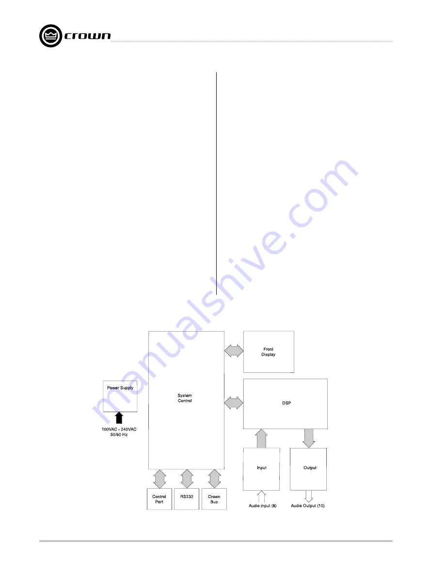
DSP Interface:
The control processor boots
all of the DSP processors via this interface.
Additionally, the control processor sets all
audio processing controls and receives all
meter data over this port.
•
•
•
•
•
Control Port:
External events can be either gen-
erated or monitored via this port and used to con-
trol or signal some function within the unit.
Sixteen digital outputs, eight digital inputs, and
eight analog inputs provide access to the unit.
current-limited voltages (+5V and +10V) are pro-
vided to power external circuits.
Digital Outputs:
These sixteen outputs pro-
vide +10V at 10 mA as configured by IQ soft-
ware. These outputs can signal either a
specific event or can signal the gate status of
the input channels.
Digital Inputs:
Eight switched inputs can be
linked to specific functions, such as muters, in
the unit. These inputs can also be used to se-
lect a particular preset based upon a desired
switch combination on these inputs. The inputs
are current driven and will accept any DC volt-
age to +25VDC.
Figure 5.1 IQ-USM 810 Circuit Block Diagram
Analog Inputs:
Any fader in the unit can be
controlled via one of these inputs. A 10VDC
swing allows the control to vary from null to full
scale. IQ software controls provide limiting of
the fader value in the unit.
•
•
•
•
•
Real Time Clock:
An internal real time clock
allows presets to be called based upon a real
time. The event scheduler works indepen-
dently of the computer and can recall a spe-
cific preset either as a one-time function or a
repeatable event with a specific start time and
repeat rate. The clock is capable of retaining
the correct time for up to 45 days without power
applied the IQ-USM 810.
•
•
•
•
•
Front Display:
The control processor commu-
nicates to the front display via a serial interface.
All LED updates and display information is
passed to the front panel in this manner. The
front-panel switches are monitored by the con-
trol processor.
•
•
•
•
•
Power Interface:
The System Controller board
receives voltages from the power supply and
routes them to the Input and DSP boards. A
regulator creates the +10V available for the
Control Port.


