

SST Modules
Page 7
Reference Manual
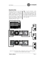
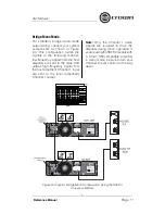
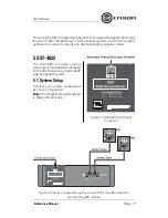
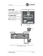
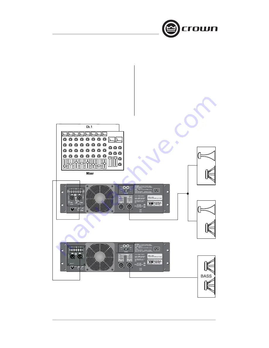
Bridge-Mono Mode
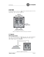
Standard bridge-mono-mode output
confi guration (shown in Figure 2.4)
routes the signal in the following
manner: low-frequency signal from
the amplifi er’s Channel 1 input is
sent to the Channel 1 barrier block
output; high-frequency signal from
Channel 1 input is sent to the local
(amplifi ed) Channel 1 output.
Note:
Only the Channel 1 audio
signal is required to drive the ampli-
fi er during mono operation. If you
are using the SST-MX module with
the amplifi er in mono mode, be sure
to turn your Channel 2 level controls
all the way down.
Figure 2.4 Typical Bridge-Mono confi guration using Crown SST-compatible
amplifi er and the SST-MX crossover module.
Summary of Contents for SST-3632
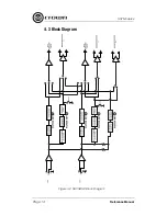
Page 14: ...SST Modules Page 14 Reference Manual Figure 4 2 SST SBSC Block Diagram 4 3 Block Diagram...
Page 32: ......
Page 34: ......


