

Rugged, Reliable, Mobile, Secure
TM
1-800-260-9800
www.CRU-DataPort.com
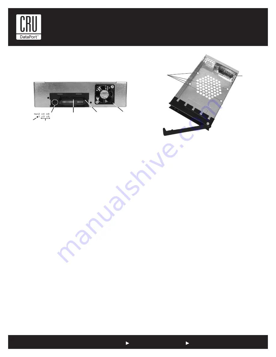
Fan Error LED Disable Switch
This switch allows the user to disable the Fan Error LED (insert a paperclip or
similar object to activate switch). CRU-DataPort recommends replacing a faulty
fan immediately. Contact CRU-DataPort for spare fan ordering information.
SATA Power Connector
15-Pin SATA power connector to accept DC power.
Note:
If your system does not accommodate the SATA power con-
nector, simply use the SATA-to-DC Power adapter cable (included in
the accessory bag) to connect to your system’s DC power.
Drive Activity LED Pins
Pin 1 is used for host connection (cable not included) to the Drive
Activity LED (Figure 2). Some SATA PC systems/host controllers provide
support for the Drive Activity LED feature (refer to the SATA PC system/
host controller manufacturer’s documentation for further information).
Factory Reserved Pins
These pins are reserved for factory use only - Do not install jumper
under any circumstances!
Cooling Fan
Field-replaceable fan provides ample cooling (4.6 CFM) for drive.
Installation
NOTE:
A #1 and #2 Phillips screwdriver will be required during this
procedure.
1. Remove the drive cover from the DX115 drive carrier and save the screws.
2. Carefully insert the drive (not included) into the carrier. Slide the
drive towards the Drive Carrier Board, so that the I/O connector on
the drive mates with the connector on the Drive Carrier Board (Figure
3). Turn the drive/carrier assembly over.
3. Fasten the drive into place with four (4) #6-32 Phillips Flat Head
screws (Figure 3). Some drives may require minor adjustment before
securing into carrier with screws.
4. Install the provided drive cover.
Limited Product Warranty
CRU-DataPort (CRU) warrants the Data Express DX115 to be free of sig-
nificant defects in material and workmanship for a period of five years
from the original date of purchase. CRU’s warranty is nontransferable
and is limited to the original purchaser.
Limitation of Liability
The warranties set forth in this agreement replace all other warranties. CRU
expressly disclaims all other warranties, including but not limited to, the
implied warranties of merchantability and fitness for a particular purpose
and non-infringement of third-party rights with respect to the documen-
tation and hardware. No CRU dealer, agent or employee is authorized to
make any modification, extension, or addition to this warranty. In no event
will CRU or its suppliers be liable for any costs of procurement of substi-
tute products or services, lost profits, loss of information or data, computer
malfunction, or any other special, indirect, consequential, or incidental
damages arising in any way out of the sale of, use of, or inability to use
any CRU product or service, even if CRU has been advised of the possibility
of such damages. In no case shall CRU’s liability exceed the actual money
paid for the products at issue. CRU reserves the right to make modifications
and additions to this product without notice or taking on additional liability.
Certification
EMI Standard:
FCC Part 15 Class B, CE CISPR B
EMC Standard:
EN55022, EN55024
This device has been tested and found to comply with the limits for a
Class B digital device, pursuant to Part 15 of the FCC rules. Operation is
subject to the following two conditions:
1. This device may not cause harmful interference, and
2. This device must accept any interference received; including
interference that may cause undesired operation
Register your product at www.CRU-DataPort.com.
A7-115-0001 Rev. 2.2
Figure 3 - Drive Installation
GND
Drive Activity
LED Pin
Reserved
Pins
SATA Power
Connector
I/O
Connector
Cooling
Fan
Bottom-mount Drive
with Four (4) #6-32
Phillips Flat Head
Screws (Provided)
Drive Carrier
Board
Figure 2 - DX115 Receiving Frame Rear Panel


