

Rugged, Reliable, Mobile, Secure
TM
1-800-260-9800
www.CRU-DataPort.com
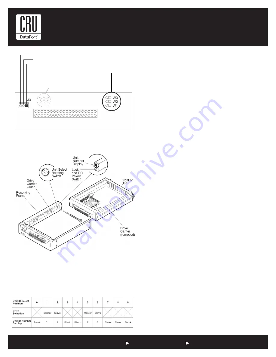
Figure 4: Unit ID Select Switch Location
NOTES:
The unit ID number display is for ID display purposes
only. The master/slave setting must be set on the drive itself.
The lock on the Data Express receiving frame functions as a lock
and a DC power switch for the carrier unit. The lock MUST be
engaged (turned counterclockwise) in order to supply power to
the carrier and installed drive unit.
Limited Product Warranty
CRU-DataPort (CRU) warrants the Data Express DE100 to be free
of significant defects in material and workmanship for a period of
five years from the original date of purchase. CRU’s warranty is
nontransferable and is limited to the original purchaser.
Limitation of Liability
The warranties set forth in this agreement replace all other warranties.
CRU expressly disclaims all other warranties, including but not limited
to, the implied warranties of merchantability and fitness for a particular
purpose and non-infringement of third-party rights with respect to the
documentation and hardware. No CRU dealer, agent or employee is au-
thorized to make any modification, extension, or addition to this warranty.
In no event will CRU or its suppliers be liable for any costs of procurement
of substitute products or services, lost profits, loss of information or data,
computer malfunction, or any other special, indirect, consequential, or
incidental damages arising in any way out of the sale of, use of, or inability
to use any CRU product or service, even if CRU has been advised of the
possibility of such damages. In no case shall CRU’s liability exceed the
actual money paid for the products at issue. CRU reserves the right to
make modifications and additions to this product without notice or taking
on additional liability.
Certification
EMI Standard:
FCC Part 15 Class B, CE
EMC Standard:
EN55022, EN55024
FCC Certification
This device has been tested and found to comply with the limits
for a Class B digital device, pursuant to Part 15 of the FCC rules.
Operation is subject to the following two conditions:
1. This device may not cause harmful interference.
2. This device must accept any interference received;
including interference that may cause undesired operation.
Register your product at www.CRU-DataPort.com
A7-100-0005 Rev. 1
Figure 3: Drive Carrier Circuit Board
Unit ID Select Switch Settings
The following table lists the unit ID select switch settings and the valid
AT/IDE unit numbers. Please note that all invalid switch settings have
shaded boxes and result in a blank display in the receiving frame window.
Drive Active Connection
Slave Connection (J3 Pin 2)
Master Connection (J3 Pin 2)
W1, W2, W3 location on
older revision boards
Drive Type Jumpers
Selecting the Unit ID Number: Use the alignment tool (provided) to
select the ID number of the disk drive.


