background image

CRU 


R T X 4 1 0 / 6 1 0 / 8 0 1 - I R   U s e r   M a n u a l   A 9 - 4 6 8 - 0 0 0 5   R E V   1 . 0  

  - 18 -          


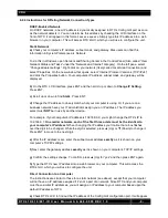
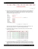
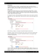
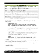
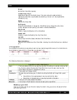
System Name 

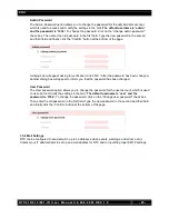
The default system name is “RTX-IR”. To change the system name, simply click in the box 
displaying the system name and highlight or delete the part of the name you wish to change, then 
type the new name and click the “Confirm” button at the bottom of the page.  


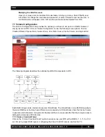
Date and Time 

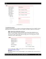
The Date and Time option allows you to change the date and time settings of RTX. To change 
the date or time, check the “Change date and time” check box and then click in the field that you 
wish to change. Highlight or delete the information, then type in the new information and click the 
“Confirm” button at the bottom of the page.  


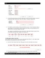
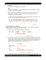
To change the time zone, click the drop down box and then scroll up or down until you reach the 
correct time zone. Then choose that time zone and click the “Confirm” button at the bottom of the 
page. 


After confirming, a dialog box will appear verifying that changes have been made.  


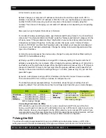
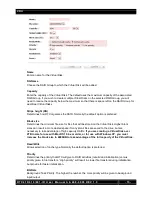
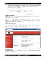
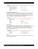
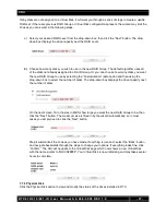
Alternatively, an NTP (Network Time Provider) can be used to sync RTX’s time information with 
that of a standardized server. To use an NTP, click the NTP check box, then input the server 
information in the server field. 


Click the “Confirm” button at the bottom of the page to update the time settings. A dialog box will 
appear to inform you that the changes have been made. The updated settings will reflect the time 
settings of the NTP. 

Summary of Contents for RTX 610-IR

Page 1: ...l Revised February 28 2012 Models covered RTX 410 IR RTX 610 IR RTX 801 IR Note The contents of this user manual reflect operational instructions for RTX IR units manufactured after 12 15 2011 RAID sets created in RTX IR units manufactured prior to this date are incompatible with newer units ...

Page 2: ... or computer 7 6 2 Use the LCD to Configure the Config GUI Port 7 7 Using the GUI 10 7 1 GUI indicators 11 7 2 Overview of GUI architecture 12 7 3 Manually Creating a Usable RAID Set 12 7 4 Quick Installation 17 7 5 System Configuration 17 7 6 ISCSI Configuration 23 7 7 Volume Configuration 26 7 8 Enclosure Management 33 7 9 Maintenance 34 7 10 Online Support 36 7 11 Logout 36 8 iSCSI Initiator so...

Page 3: ...act CRU DataPort if any items are missing or damaged RTX 410 IR and 610 IR RTX Unit 1 Power Cord 1 Ethernet Cable 2 Packet of DataPort Keys 1 2 2 Identifying the Parts of RTX LCD Panel on front of RTX Ports on rear of RTX 2 3 Warnings and Notices Please read the following before beginning installation General Care RTX Unit 1 Power Cord 1 Ethernet Cable 2 Packets of Lock Tools 2 LCD Up ESC escape e...

Page 4: ... of the drives and offers the best data transfer speeds However RAID 0 offers no protection for the data If one drive fails in a RAID 0 the data on all of the drives is irretrievably lost Before creating a RAID investigate the various RAID types and choose the one that is best for your needs Always back up data before switching RAID types Switching RAID types will destroy current data You must ref...

Page 5: ...d the failure of one drive The total capacity of all but one of the drives is available for data storage 3 1 drive Reads are similar to RAID 0 6 Two parity bits are used to create double redundancy Can withstand the failure of two drives The total capacity of all but two of the drives is available for data storage 4 2 drives Slightly less than RAID 5 0 1 Also known as a mirror of striped drives Da...

Page 6: ...uilt in server capabilities and therefore cannot be accessed by more than one computer at a time Multiple computers can only access the data if the iSCSI device is first attached to a single computer which is then set up as a server 5 Installation Steps 5 1 Hard Drive Installation a Pull the ejection handle on the TrayFree bay to open the bay door b Insert a bare SATA hard drive into the bay Make ...

Page 7: ...nection is not available you can connect the Ethernet cable directly to an RJ45 Ethernet port on your computer c Connect the power cable to the rear of RTX and to a grounded electrical outlet d Turn on RTX s power using the switch on the rear panel 6 2 Using the LCD to Configure the Config GUI Port RTX has both an LCD interface and a GUI The LCD interface has only basic functionality and is mainly...

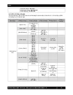
Page 8: ...Version x x x RAM Size xxx MB Alarm Mute ENT OK ESC Back Reset Shutdown Reboot ENT OK ESC Back Shutdown ENT OK ESC Back Quick Install RAID 0 RAID 1 RAID 3 RAID 5 RAID 6 RAID 0 1 xxx GB Apply The Config ENT OK ESC Back Volume Wizard Local RAID 0 RAID 1 RAID 3 RAID 5 RAID 6 RAID 0 1 Use default algorithm Volume Size xxx GB Apply The Config ENT OK ESC Back View IP Setting IP Config Static IP IP Addre...

Page 9: ... Change the IP address to closely match what your computer is using Or if you are on a business network have your IT administrator assign you an IP address The IP address you select must NOT be in use by another device For example if your computer s IP address is 192 168 0 9 you might change the RTX s IP to 192 168 0 7 On smaller networks each of the first three octets must be the identical to you...

Page 10: ...t a box flashes over the digit to be changed While the digit is selected press Up or Down to change it Press ENT to move to the next digit After the gateway address is set press ENT all the way to the end and confirm the settings change To confirm press Up for yes and then press ENT again e Launch a web browser and type RTX s IP address into the URL bar as if it were a website This will access RTX...

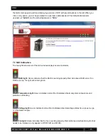
Page 11: ...rner of the GUI window displays several indicators RAID light Green indicates that the RAID is working properly Red indicates a RAID error If no RAID is set up the light will remain green Temperature light Green indicates normal Red indicates abnormal system temperature and probable overheating Voltage light Green indicates normal Red indicates abnormal voltage status like a power surge or a bad p...

Page 12: ...configuration o Hardware monitor o S M A R T Maintenance o System information o Upgrade o Reset to factory default o Import and export o Event log o Reboot and shutdown Online support o Product Information and Specs o FAQ and Downloads Logout 7 3 Manually Creating a Usable RAID Set Use these sets of instructions to create a usable RAID set To quickly create a RAID 0 1 3 5 6 or 0 1 set using the Vo...

Page 13: ...o the RAID Group Note Drives must be marked as Free Disks before they can be added to a RAID Group To set drives to Free Disks see Section 7 7 2 subsection Modifying Physical Disks c All available Free Disks will be displayed Check the drives that you wish to add to the RAID Group then click Confirm d The selected Physical Disks will now be displayed in the RAID Group creation screen Enable or Dis...

Page 14: ...attached Go to the next section Manually Creating a Virtual Disk If you opted to create JBOD drives skip to Section 8 3 3 Manually Attaching a Logical Unit as Virtual Disks have already been created for each JBOD drive 7 3 2 Manually Creating a Virtual Disk After a RAID Group has been created you can create associated Virtual Disks You must create at least one Virtual Disk to access the drives of ...

Page 15: ... that will be stored on the Virtual Disk Higher block sizes can result in more wasted space if many small files are saved to the drive but are necessary to take advantage of high capacity RAIDs If you are creating a Virtual Disk over 2TB in size for use with MacOS 10 4 x or older or for use with Windows XP you must increase the block size to 4096KB to take advantage of the full capacity of the Vir...

Page 16: ... Logical Unit 7 3 3 Manually Attaching a Logical Unit You will need to attach at least one Logical Unit to a Virtual Disk to access its RAID Group although multiple Logical Units can be attached to the same Virtual Disk a Click the Attach button to attach a Logical Unit to a Virtual Disk b You will see the screen below Fill in the information Select the Virtual Disk to which you wish to attach a L...

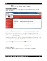
Page 17: ...stall uses all physical disks in RTX and the maximum amount of space they contain to create a RAID Group using one Virtual Disk There will be no space set aside for spares If some disks are used in other RAID Groups Quick Install cannot be run 7 5 System Configuration The System Configuration menu gives access to a number of options used to configure RTX system properties Click on System Configura...

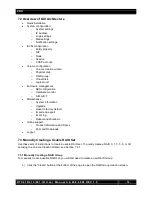
Page 18: ...ion then type in the new information and click the Confirm button at the bottom of the page To change the time zone click the drop down box and then scroll up or down until you reach the correct time zone Then choose that time zone and click the Confirm button at the bottom of the page After confirming a dialog box will appear verifying that changes have been made Alternatively an NTP Network Time...

Page 19: ...administrator to configure the IP address of the individual data ports This must be done using the LCD interface on the front of RTX Section 6 2 An RTX configured for DHCP 7 5 3 Login Settings The Login Settings page allows you to configure the Auto Logout and Login Lock features as well as change the administrator account and user passwords Login Configuration Auto Logout will automatically log t...

Page 20: ...lick OK After the password has been changed another dialog box will appear to inform you that the password has been changed User Password The User password option allows you to change the password for the user account which is used to view but not modify the settings in the GUI The default username is user and the password is 1234 To change the password click on the Change user password check box ...

Page 21: ...t Protocol SNMP can be configured to send trap messages to up to three different addresses on the network To add an address simply enter the IP address of the receiving server or computer then click the Confirm button at the bottom of the page Note The receiving server must be configured to receive SNMP messages For more information on SNMP you may wish to consult the third party website http www ...

Page 22: ... boxes for Info Error and Warning that pertain to the information that you want to have reported Event Log Filter The Event Log Filter allows you to display event messages To configure what types of messages are displayed select the check boxes for Info Error and Warning that pertain to the information that you want to have reported The options for Pop Up Events will display those events as a pop ...

Page 23: ...perty NIC Node Session and CHAP Account 7 6 1 Entity Property The Entity Property option allows you to add an Internet Storage Name Service iSNS server IP address to the iSNS server group to which the iSCSI initiator can send queries Simply enter the iSNS IP address in the iSNS IP field and click Confirm Note Setting an iSNS is not necessary to use RTX 7 6 2 NIC Click on NIC to view the IP setting...

Page 24: ...ion in order to enable DHCP or to manually set up a channel s IP Address Netmask and Gateway Fill in the appropriate information and then click the Confirm button Set the Default Gateway Sets the selected channel as the default gateway for RTX To disable the default gateway hover your mouse cursor over the appropriate button in the Name column again and select the Disable default gateway option On...

Page 25: ...arious times during the connection by way of transferring the username initiator password also called initiator secret and target password also called target secret RTX uses the same value for initiator secret and target secret For added security the authentication information is hashed and a token is sent instead of the information itself a To use CHAP you will need to turn on CHAP authentication...

Page 26: ...llowing menu options Volume Creation Wizard Physical Disk Volume Group User Data Volume Cache Volume and Logical Unit The following diagram describes the relationship of RAID components in RTX Each RAID Group can be divided into several Virtual Disks The Virtual Disks in one RAID Group share the same RAID level but may have different volume capacity All Virtual Disks share the Cache Volume to exec...

Page 27: ... selecting the Customization radio button and then using the drop down box to select the number of disks The drop down box displays the drive capacity next the number of disks On the next screen fill in the size in MB for how large you want the new RAID Group to be then click the Next button The maximum size is filled in by the wizard automatically so in most cases you simply need to click the Nex...

Page 28: ...general operational health of the disk Good The hard drive is good Failed The hard drive has failed Error Alert The hard drive s S M A R T monitoring system is reporting an error Read Errors The hard drive has unrecoverable read errors Usage Displays how the disk is currently being used RAID Disk RD The hard drive has been assigned to a RAID Group Free Disk FD The hard drive is free for use Dedica...

Page 29: ...its data Upgrade Opens a page that allows the administrator to upgrade the hard drive firmware The administrator may simultaneously upgrade all the hard drives in RTX that are identical to the one selected Turn on Indication LED Turns on the indication LED for the bay in which the physical disk resides More information Displays more details about the hard drive 7 7 3 RAID Group The RAID Group scre...

Page 30: ...l or add disks to the RAID without data loss The total size of the new RAID Group must be larger or equal to the original RAID Group or the action will trigger an Invalid RG config error Move Allows the administrator to change which disks on which the RAID Group exists without losing data The total size of the new RAID Group must be larger or equal to the original RAID Group or the action will tri...

Page 31: ...ual Disk is being rebuilt Migrate The Virtual Disk is being migrated Rollback The Virtual Disk is being rolled back Parity Checking The Virtual Disk is undergoing a parity check Type Indicates that the Virtual Disk is part of a RAID Group Health The health of the Virtual Disk Optimal The Virtual Disk is working well and there is no failed physical disk within the RAID Group Degraded At least one d...

Page 32: ...ached to it 7 7 5 Logical Unit The Logical Unit is what your computer will use to access and manage SCSI devices For instructions on how to attach a Logical Unit to a Virtual Disk see Section 7 3 3 The following information is displayed Logical Unit Column Descriptions Host The host address which can access the attached Virtual Disk An asterisk indicates that any host may access the attached Virtu...

Page 33: ...lays indicators and individual drives of a SCSI device RTX is an SES compliant enclosure However in order to use manage RTX using SES you must have the appropriate software installed on your computer An example is SMARTMon a S M A R T disk monitor offered by Santools at www santools com To enable SES on RTX you must have a Virtual Disk set up and a Logical Unit attached Once you have done this nav...

Page 34: ... for hard drives that gives advanced warning in some cases of hard drive failure S M A R T measures various attributes of a hard drive at all times to detect if certain values have moved outside of a certain range The S M A R T option allows you to view the S M A R T status of all of your hard drives RTX s S M A R T technology only supports SATA drives SAS drives do not have this function and will...

Page 35: ...STRUCTION FROM CRU DATAPORT TECHNICAL SUPPORT Doing so could result in malfunction of your RTX 7 9 3 Reset to Factory Default The Reset to Factory Default option allows you to restore settings to the factory defaults Click on the Confirm button to verify 7 9 4 Import Export The Import Export function allows you to import or export a firmware configuration file DO NOT USE THIS FUNCTION WITHOUT SPEC...

Page 36: ...of and exit the GUI 8 iSCSI Initiator Software 8 1 Software Installation This is a required step Any computer must have initiator software installed before it can connect to an iSCSI device such as RTX Both freeware and commercial software utilities are available for this purpose Note Initiator software is not required for additional computers that share files with the host computer attached to RT...

Page 37: ... on the Quick Connect button If the log on is successful you ll now be able to use the RTX just like any other disk attached to your computer Note The Quick Connect feature does not support advanced connection types like CHAP For instructions on connecting to an iSCSI target using advanced settings visit the following URL http technet microsoft com en us library ee338480 v ws 10 aspx BKMK_ConnectA...

Page 38: ... you are using the globalSAN initiator you log off from the Targets tab Disconnecting in this way allows you to reconnect quickly later Another way of preventing delays is to keep your iSCSI initiator software open at all times You can minimize it and allow it to run in the background Closing the software and then reopening it can cause a lengthy delay before access to RTX is allowed NOTE It is st...

Page 39: ...ection of a file system Choose NTFS and enter a name for the new volume Be sure to check the box labeled Perform a quick format unless you want to completely erase any data on the drive and have time to wait A quick format should take less than a minute while standard formatting may take several hours g Click Next and then Finish to start the format process When the format is complete the Drive Pr...

Page 40: ...data loss nor do the warranties of other hard drive manufacturers Plan accordingly and backup data to minimize downtime 11 Event Notifications Physical Disk Events Level Type Description Info PD inserted Disk slot is inserted into system Warning Disk removed Disk slot is removed from system Error HDD read error Disk slot read block error Error HDD write error Disk slot write block error Error HDD ...

Page 41: ...System overheated string Error Thermal level 2 shutdown System overheated string The system will auto shutdown immediately Error Thermal level 2 CTR shutdown The controller will auto shutdown immediately reason Overheated string Warning Thermal ignore value Unable to update thermal value on string Warning Voltage level 1 System voltage string is higher lower Error Voltage level 2 System voltages s...

Page 42: ...ing VD init failed Failed to complete initialization of VD name Info VD rebuild started VD name starts rebuilding Info VD rebuild finished VD name completes rebuilding Warning VD rebuild failed Failed to complete rebuild of VD name Info VD migrate started VD name starts migration Info VD migrate finished VD name completes migration Error VD migrate failed Failed to complete migration of VD name In...

Page 43: ...address address of PD slot Warning PD write error Write error occurted at LBA address address of PD slot Warning Scrub wrong parity The parity data inconsistency is found at LBA address address when checking parity on VD name Warning Scrub data recovered The data at LBA address address is recovered when checking parity on VD name Info PD freed PD slot has been freed from RG name Info RG imported C...

Page 44: ...process Info Failback complete All volumes in controller number completed failback process Info CTR inserted Controller number is inserted into system Error CTR removed Controller number is removed from system Error CTR timeout Controller number gets no response Error CTR lockdown Controller number is locked down Error CTR memory NG Memory size mismatch Error CTR firmware NG Firmware version misma...

Page 45: ... the IP address under the iSCSI configuration menu nothing happens A Sometimes when you first set up RTX you ll need to reattach the Logical Unit if it doesn t work the first time Q How many computers can connect to one data volume on the iSCSI unit A The short answer is one computer to one volume This is the safest and suggested usage of RTX If two people are accessing files on the same volume at...

Page 46: ...k Attached Storage A The difference between iSCSI and NAS is that a NAS does not need a computer to act as a server Q I put my computer to sleep and now it s having trouble reconnecting to RTX How can I prevent this A To prevent difficulties such as this follow the shutdown procedure documented in the LCD menu diagram in Section 6 2 3 CRU DataPort also suggests that you disable automatic sleep on ...

Page 47: ...arranties of merchantability and fitness for a particular purpose and non infringement of third party rights with respect to the documentation and hardware No CRU dealer agent or employee is authorized to make any modification extension or addition to this warranty In no event will CRU or its suppliers be liable for any costs of procurement of substitute products or services lost profits loss of i...

Reviews: