8-12
520 Express Series
520 Express Series
GENERAL MAINTENANCE
Power Train
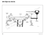
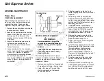
COUPLING ALIGNMENT
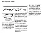
Slight coupling misalignment can cause
vibrations, loss of power and damage to
crankshaft bearings. Check coupling
alignment using the following procedure:
1. Remove the coupling bolts and slide the
coupling apart only slightly.
2. Measure the gap between the coupling
halves at four places 90° apart with a
feeler gauge. The difference in the
readings must not exceed 0.003 inches
(0.08 mm).
3. Adjust the adjustable engine mounts,
until engine and coupling are in
alignment. See your Cruisers Yachts
Dealer if necessary.
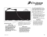
4. Leave coupling half on transmission
stationary and rotate the propeller shaft
1 turn, in 90° intervals. At each 90°
interval, check the clearance between
the coupling halves. If the four
measurements differ by more than 0.003
inches (0.08 mm), the propeller shaft
may be bent.
PROPELLER REPLACEMENT
WARNING
Avoid accidental starting of the
engines when changing propellers.
Remove the keys from the ignition
switches.
Protect your hands. Propellers can
have sharp edges and are heavy.
Handle with care.
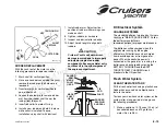
The following steps represent a typical
propeller installation procedure. Refer to the
propeller manufacturer’s recommended
procedure if different.
1. Remove any small burrs on tapered end
of propeller shaft using a honing stone.
2. Apply a thin layer of Prussian Blue
blueing compound on the tapered
section of the shaft.
3. Slide the propeller on the shaft and
rotate it slightly on the shaft. Remove the
propeller.
4. The blueing will be gone where the
propeller contacts the shaft. About 60%
contact is required between the propeller
and the shaft. If sufficient contact area is
obtained, go to Step 7.
5. If the contact area is small, apply a
course valve grinding compound to the
taper of the shaft. Install the propeller
and rotate it on the shaft clockwise and
counterclockwise about 100 times.
6. Remove the propeller and clean the
grinding compound from the shaft and
propeller. Repeat Steps 2 to 4.
7. Apply a light layer of waterproof grease
to taper area of shaft.
8. Install the key and propeller on the shaft.
The key should fit tight from side to side.
There should be a slight clearance
between the top of the key and the
groove in the propeller. If there is no
clearance, the propeller can be forced off
center causing vibration.
9. Drive the propeller all the way up the
shaft by installing and tightening the
large nut.
10. Install the small nut. Hold the large nut
while tightening the small nut to lock the
nuts in place. Install the cotter pin and
bend the ends over to hold it in place.
CSR161-36A
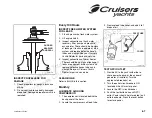
COUPLING
TRANSMISSION
MISALIGNED COUPLING
Downloaded
from
Cruisers
Owners
Forum
http://www.CruisersOwnersForum.com

