Assembly Instructions
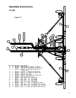
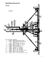
32' Drill
The main and wing sections are pre-assembled at the factory to simplify final assembly. Extreme caution should
be taken during assembly for safety. Use sturdy stands in the proper places and use dependable lifting devices
for heavy parts. Lay out parts in an area which allows enough room for crane, winch truck, or other safe lifting
device to assemble drill.
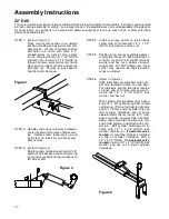
STEP 1
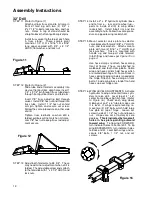
(Refer to Figure 1)
Place main center section in an upright
position standing on hoe points and suit-
able stands. Lift rear of A-frame to align
bolt holes in A-frame with holes in L-
shaped plates on front of main center
frame. Secure with four (4) 1" x 5" HHCS
and lock nuts. Install 1" x 2 1/2" HHCS up
through A-frame plate and center frame
plate on each side of A-frame and secure
with lock nut. Pin jack to jack spool to
hold front of A-frame up.
Figure 1
STEP 2
Spindles and hubs are factory installed in
center rockershaft to lessen field assem-
bly. Rotate center rockershaft up and
install four (4) 6 bolt rim and tire assem-
blies to hubs.
STEP 3
(Refer to Figure 3)
Rotate rockershaft down and install 4" x 8"
hydraulic cylinder base end to A-frame lug
(ram end to rockershaft lug) and ports to
left side of drill.
Figure 3
STEP 4
Install one hose carrier to tab on back
center stub of A-frame with 1/2" x 1 1/2"
HHCS, lock washer, and hex nut.
STEP 5
Position wing carrier assembly approxi-
mately two inches (2") behind fold lug on
A-frame. Insert 3/4" x 6" HHCS with lock
washer and hex nut in bottom clamp of
wing carrier. DO NOT tighten now - wing
carrier may need to be adjusted when
wings are folded.
STEP 6
(Refer to Figure 6)
Slide fold slide onto slide bars with cylin-
der hole toward U-clamp on slide bars.
Put slide bars into the two tubes located
on back end of A-frame and secure U-
clamp with 1/2" x 5 1/2" HHCS, lock
washer, and hex nut.
With cylinder pins provided, attach base
end of 3" x 30" hydraulic cylinder to fold
cylinder lug. (Ports of cylinder to right side
of drill.) Lift ram end of cylinder and slip
fold cylinder hold-down over A-frame
approximately twenty inches (20") from
base of cylinder. Lower cylinder into hold-
down, move fold slide to align with ram
end of fold cylinder, and attach with cylin-
der pin. Bolt cylinder hold-down to A-
frame with 1/2" x 5 1/2" HHCS, lock
washer, and hex nut.
If a selector valve
is used
, its mounting bracket is installed
on top of cylinder hold-down with a
1/2" x 5 1/2" HHCS.
If no selector valve
is used,
install a 1/2" x 4 1/2" HHCS, lock
washer, and hex nut in top of cylinder
hold-down.
Figure 6
10
Summary of Contents for 3200
Page 1: ...3200 Trash Shank OWNER S MANUAL 01 10 601401 ...
Page 5: ...Safety RECOGNIZE SAFETY INFORMATION UNDERSTAND SIGNAL WORDS FOLLOW SAFETY INSTRUCTIONS 3 ...
Page 6: ...Safety OPERATE SAFELY AVOID TIP OVERS KEEP RIDERS OFF MACHINE 4 ...
Page 7: ...Safety HANDLE FUEL SAFELY AVOID FIRES PREPARE FOR EMERGENCIES WEAR PROTECTIVE CLOTHING 5 ...
Page 8: ...Safety USE SAFETY LIGHTS AND DEVICES TRANSPORT SAFELY 6 ...
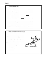
Page 9: ...Safety TOW LOADS SAFELY PRACTICE SAFE MAINTENANCE 7 ...
Page 10: ...Safety AVOID HIGH PRESSURE FLUIDS CHARGE ROW MARKER HYDRAULIC SYSTEM 8 ...
Page 34: ...32 A Frame 32 ...
Page 36: ...40 A Frame 34 ...
Page 38: ...Center Frame Section 36 ...
Page 40: ...32 Left Wing Section 38 ...
Page 42: ...32 Right Wing Section 40 ...
Page 44: ...40 Left Wing Section 42 ...
Page 46: ...40 Right Wing Section 44 ...
Page 48: ...Center Drive Assembly 46 ...
Page 50: ...Left Drive Assembly 48 ...
Page 52: ...Right Drive Assembly 50 ...
Page 54: ...Box Assembly 52 ...


