Cryo-con Model 24C
Basic Setup and Operation
Thermocouple Device Installation
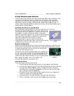
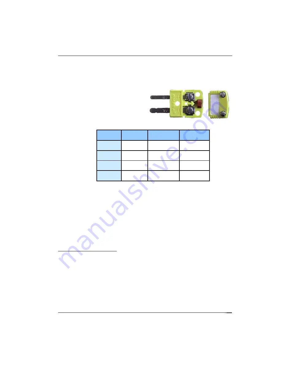
The thermocouple device must first be connected to a standard thermocouple mini-
spade connector of the proper type. Wires are attached using the screw terminals.
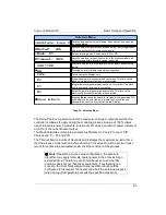
Polarity is marked on the input connector and a summary of common thermocouple
types is given in the table below. The
input connector should have its plastic
back-shell and rubber grommet installed
in order to prevent local air currents from
generating errors in the cold junction
circuitry.
Type
Connector
Color
(+) Terminal
(-)Terminal
E
Purple
Chrome
Purple
Constantan
Red
K
Yellow
Chrome
Yellow
Aluminum
Red
T
Blue
Copper
Blue
Constantan
Red
Chromel-
AuFe
White
Chromel
Silver
Gold
Gold
Table 35: Thermocouple Polarities
Note that the Chromel-AuFe device is a special cryogenic device. The connector
used is White, indicating a type U (unspecified) device.
Grounded vs. Floating Thermocouples
Electrically floating devices are always recommended because they provide generally
lower noise operation and cannot facilitate ground-loop conditions. However, the
thermocouple module inputs are differential and have a high impedance to ground.
This will allow operation with grounded devices in most systems. Always ensure that
there is no more than a 5V difference between the grounded thermocouple and the
instrument's chassis ground.
Common Installation Issues
Cold Junction Compensation
Cold Junction Compensation in the Cryo-con thermocouple module is performed by a
circuit that measures the temperature of the input connector pins. This reading is then
used offset the device's output voltage. Errors can be minimized by reducing local air
currents around the module.
97

