Cryo-con Model 24C
Appendix A: Installed Sensor Curves
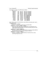
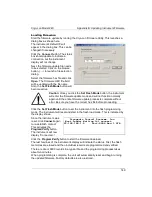
Sensor Curves on CD
The following sensors are available on the CD supplied:
File
Description
Cryocon S700
Cryo-con S700 series Silicon diode. Range: 1.4 to 500K.
10
m
A constant current excitation.
CryocalD3.crv
Cryocal D3 Silicon diode. Range: 1.5 to 300K
SI410.crv
Scientific Instruments, Inc. SI-410 Silicon diode. Range: 1.5 to 450K
Curve10.crv
Lakeshore Curve 10 Silicon diode curve for DT-470 series diodes.
Range: 1.4 to 495K.
Curve11.crv
Lakeshore Curve 10 Silicon diode curve for DT-670 series diodes.
Range: 1.4 to 500K.
PT100385.crv
Cryocon CP-100, DIN43760 or IEC751 standard Platinum RTD, 100
W
at 0
°
C.
Range: 23 to 1020K
PT1K385.crv
DIN43760 or IEC751 standard Platinum RTD, 1000
W
at 0
°
C.
Range: 23 to 1020K
PT1003902.crv
Platinum RTD, 100
W
at 0
°
C Temperature coefficient 0.003902
W
/C.
Range: 73K to 833K.
PT1K375.crv
Platinum RTD, 1000
W
at 0
°
C Temperature coefficient 0.00375
W
/C.
Range: 73K to 833K.
aufe07cr.crv
Chromel-AuFe 7% thermocouple. Range: 3 to 610K
TCTypeE.crv
Thermocouple, Type E. Range: 3.2 to 1273K
TCTypeK.crv
Thermocouple, Type K. Range: 3.2 to 1643K
TCTypeT.crv
Thermocouple, Type T. Range: 3.2 to 673K
CX1030E1.crv
Cernox™ CX1030 example curve. Range: 4 to 325K
User Calibration Curve File Format
Sensor calibration curves may be sent to any Cryo-con instrument using a properly
formatted text file. This file has the extension .crv. It consists of a header block, lines
of curve data and is terminated by a single semicolon (;) character.
The header consists of four lines as follows:
Sensor Name: Sensor name string
Sensor Type:
Enumeration
Multiplier:
Signed numeric
Units:
Units of calibration curve: {OHMS | VOLTS | LOGOHM}
The Sensor Name string can be up to 15 characters and is used to identify the
individual sensor curve. When downloaded to a Cryo-con instrument, this name
appears in the sensor selection menu of the embedded web server and will appear on
all sensor selection fields on the front panel.
The Sensor Type Enumeration identifies the required input configuration of the input
channel. For the Model 24C, selections are: DIODE, PTC100, PTC1K, NTC10uA,
TC70, NONE and ACR. These configurations are described in the section titled
Supported Sensor Configurations
.
143

