Cryo-con Model 24C
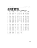
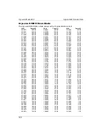
Appendix A: Installed Sensor Curves
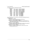
The following is an example of a calibration curve transmitted to the instrument via
the LAN interface:
Good Diode
Diode
–1.0
volts
0.34295 300.1205
0.32042 273.1512
0.35832 315.0000
1.20000 3.150231
1.05150 8.162345
0.53234 460.1436
;
In summary,
1. Lines must always be terminated by a line-feed character (\n). Carriage-
return characters (\r) are ignored.
1. The first line is a name string that can be up to 15 characters. Longer strings
are truncated by the instrument.
The second line identifies the instrument's input configuration and must be
one of the allowed selections described in the
Supported Sensor
Configurations
section.
2. The third line is the multiplier field and is 1.0 for PTC sensors and -1.0 for
NTC sensors or diodes.
3. The fourth line of the header is the sensor units and must be Volts, Ohms or
Logohm.
4. Curve entries must be the sensor reading followed by the temperature in
units of Kelvin. Values are separated by one or more white space or tab
characters.
5. The last line in the file has a single semicolon ( ; ) character. All lines after this
are rejected.
6. It is recommended that the curve back is read after downloading to ensure
that the instrument parsed the file correctly. This is easily done by using the
Cryo-con utility software’s curve upload function under Operations>Sensor
Curve>upload.
145

