Cryo-con Model 24C
Appendix H: Rear Panel Connections
Ethernet (LAN) Connection
The Ethernet connection on the Model 24C uses a standard RJ-45 connector with
two LEDs that are used to indicate status.
When connecting the Model 24C to a hub or switch, a standard Category 5 'patch’
cable is used.
When connecting the Model 24C directly to the computer a
crossover cable
should
be used.
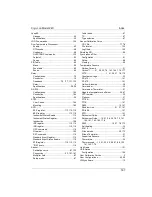
The RJ-45 LAN connector has two LEDs. The left most LED indicates that a valid
connection has been made to a hub or computer.
If the LAN is plugged in and the ‘Connected’ LED is not on,
there is a problem that must be addressed before you can
communicate with the instrument.
The right most LED indicates activity on the LAN. It should
flicker periodically during normal operation.
IEEE-488.2 Connections
The optional IEEE-488.2 (GPIB) connection is installed by connecting the dongle to
the Ethernet port using the crossover LAN cable provided. The interface will be
configured by the instrument and will appear to your system as a standard IEEE-
488.2 device.
RS-232 Connections
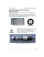
The Model 24C uses a Female DB-9 connector for RS-232 serial communications.
The pin-out of this connector is as follows:
Pin
Function
Pin
Function
1
NC
6
NC
2
RXD, Receive data
7
NC
3
TXD, Transmit data
8
NC
4
NC
9
NC
5
Ground
Table 42: RS-232 DB-9 Connector Pinout
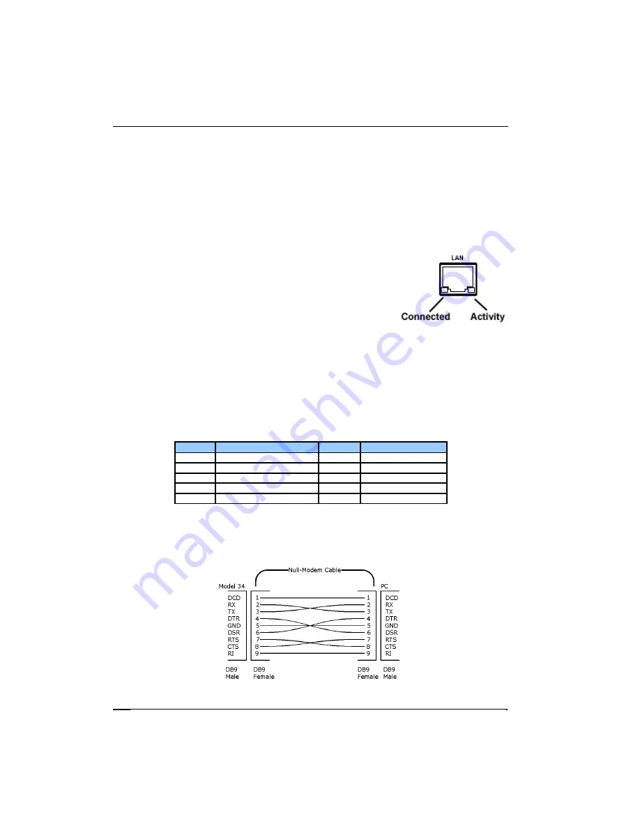
The cable used to connect the Model 24C to a computer serial port is a Dual Female
Null Modem cable. An example is Digikey Inc. part number AE1033-ND.
Figure 9: RS-232 Null Modem Cable
184

