Cryo-con Model 24C
Front Panel Menu Operation
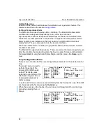
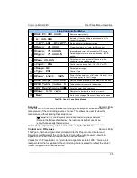
Loop Configuration Menu
1
Set Pt:300.000K
Numeric setpoint entry.
2
A: 299.99K
Indicator of the controlling input channel and it's
current temperature.
3
1-Off-LOW -Htr-Off-
Status indicator for the control loop.
4
Proportional gain, or P term for PID control.
5
Integrator gain term, in Seconds, for PID control.
6
Derivative gain term, in inverse-Seconds, for PID
control.
7
Output power, as a percent of full scale, when
controlling in the Manual mode
.
8
+
Control input channel, ChA , ChB, ChC or ChD.
9
+
Output power range.
10
+
Control Type
11
Power limit as a percent of full scale. On loop 1, this
limit only applies to the HI range.
12
Maximum value allowed for the setpoint on this loop.
13
Table number for control in Table mode.
14
+
Sets the heater load resistance.
15
Ramp rate in temperature units per minute.
16
Next
Go to the next page of the control loop setup menu.
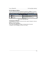
Table 18: Control Loop Setup Menus.
Setpoint
Numeric Entry
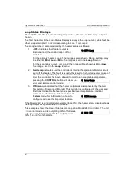
In the first line of this menu the user can change the setpoint, while still viewing the
temperature of the controlling source channel. This allows the user to view the
temperature without leaving the setup menu.
i
Note:
Entry of a setpoint can be overridden by the Maximum
Setpoint field described below. The instrument will not accept an
entry that exceeds the maximum.
Control loop setpoints may also be entered by using the
Set Pt
key.
Control Loop PID values
Numeric Entry
The Pgain, Igain and Dgain lines correspond to the Proportional, Integral and
Derivative coefficients of the control loop. Pman is the output power that will be
applied to the load if the manual control mode is selected.
Values for the Proportional, or P, gain term range from zero to 1000. This is a unit-
less gain term that is applied to the control loop. Gain is scaled to reflect the actual
heater range and the load resistance.
55

