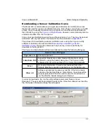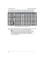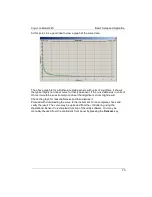
Cryo-con Model 24C
Basic Setup and Operation
NTC Sensor Configuration
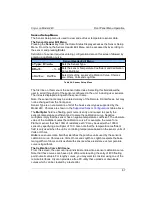
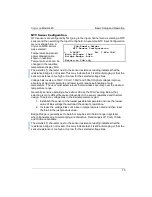
NTC sensors are configured by first going to the input channel menu, selecting a NTC
sensor and then selecting the Input Config field. An example NTC Input Configuration
menu is shown here. A
Cryo-con R500 sensor
was selected.
Temperature and sensor
power dissipation are
shown in real-time.
Temperature units can be
changed in the real-time
temperature display field.
The asterisk (*) character next to the sensor resistance reading indicates that the
resistance bridge is not locked. This may indicate that it is still autoranging or that the
sensor resistance is too high or too low for the selected voltage bias.
Voltage bias levels are 10mV, 3.0mV, 1.0mV and 300uV. Higher voltages improve
accuracy at warm temperature and lower levels reduce self-heating at cold
temperature. The user must select a level that maximizes accuracy over the desired
temperature range.
Generally, sensors operating above about 2K use the 10mV setting. Below that,
selection is more difficult because it depends on the sensor resistance and thermal
design. To select a voltage bias in the low temperature region:
1. Establish the sensor at the lowest possible temperature and use the lowest
value of bias voltage that will read the sensor's resistance.
2. Increase the voltage bias until a rise in temperature is noted and then reset
the bias to the just previous value.
Bridge Range is generally set to Auto but may be set to hold a range in systems
where transients due to autoranging are disruptive. Fixed ranges of 1.0mA, 100uA
and 10uA are available.
The asterisk (*) character next to the sensor resistance reading indicates that the
resistance bridge is not locked. This may indicate that it is still autoranging or that the
sensor resistance is too high or too low for the selected voltage bias.
75
ChA:Sample Holder
NTC Sensor Configuration
+ 0.241K* Pd: 1.66e-10W
Bias Voltage: 10mV
Bridge Range: Auto
Return to ChA cfg


