Cryo-con Model 24C
Basic Setup and Operation
Ramping Algorithm
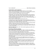
The ramp algorithm uses a basic PID type control loop and continuously varies the
setpoint until the specified temperature is reached. This means that the PID control
loop will continuously track the moving setpoint. The result is that there will be small
time lag between the target ramp and the actual temperature.
Although not normally a problem, the ramp time lag may be minimized by using
aggressive PID values. This is accomplished by increasing P, decreasing I and setting
D to zero.
Ramping Parameters and Setup
The Ramp Rate is set on the Control Loop Setup menu. Note that the ramp rate on
Loop 1 is independent of the rate on Loop 2.
Ramping Example
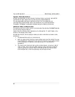
First, the controller must have PID tuning values that give stable temperature control
at both the beginning and end of the ramp. The PID values are usually ‘slow’ (Low
values for P, high for I and zero for D). The actual values are not critical, they just
need to give stable control.
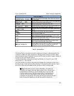
Next, set the control type to RampP and set the desired ramp rate in the Heater
Configuration Menu. Then set the loop setpoint to the
starting
value for the ramp.
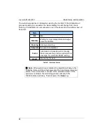
The best way to view a temperature ramp is from the control loop status. Press Loop
1 key to view a screen like
this:
Here, the instrument is not
controlling temperature
and the ramp will start at
180K.
When the
Control
button is pressed, the controller will go to the setpoint and control
temperature there. It is
NOT yet ramping! The
display will look like this:
86
Loop 1A:Sample Holder
Set Pt:180.000K
Pgain: 5.0000
Igain: 120.00S
Dgain: 0.0000/S
Pman: 5.0000%
Type: RamP
Input: ChA
A: 175.234K
1-Off-Low -Htr-Off
Range: HI
PID Table index: 1
Htr Load: 50
W
Next
Loop 1A:Sample Holder
Set Pt:180.000K
Pgain: 5.0000
Igain: 120.00S
Dgain: 0.0000/S
Pman: 5.0000%
Type: RamP
Input: ChA
A: 180.000K
51% HI
---|
Range: HI
PID Table index: 1
Htr Load: 50
W
Next
Controlling at 180K but NOT ramping


